VPC
VPC in Zadara Cloud Services
The VPC construct in Zadara Cloud Services was designed to provide a user experience that is identical to the AWS VPC. The virtual private cloud provides a routed L3 environment into which the user can deploy instances and managed services.
Virtual Private Cloud (VPC)
The VPC is a networking resource with a logical router at its core. When you create a VPC you specify a CIDR block. All subnets that you will create in the VPC will be carved out from this CIDR block (without overlap). The router will ensure IP connectivity between all these subnets.
Subnet
VPC subnets are defined by the following constraints:
The CIDR block of a subnet may be either identical to the VPC’s CIDR block, which is the case when there is a single subnet, or a subset of the VPC’s CIDR block, when there are multiple subnets. In the latter case, the CIDR blocks of the subnets cannot overlap.The permitted block size ranges from a /28 netmask to a /16 netmask.
The first four IP addresses and the last IP address in each subnet CIDR block are not available for users, and cannot be assigned to an instance.
The second address of the subnet is reserved for the router.
Every subnet that is created is automatically associated with the main route table of the VPC. You can change the association. A subnet can be associated with only one route table at a time.
Internet Gateway (IGW)
An internet gateway is a logical entity that connects the VPC router to an external network. It is used as a target in the VPC route tables for Internet-routable traffic.
Route Tables
Route tables control the IP forwarding of all traffic in the subnets with which they are associated.
A VPC comes with a single built-in, modifiable, main route table.
You can create additional custom route tables for your VPC.
You cannot delete the main route table, but you can replace the main route table with a custom table that you’ve created. This table becomes the default table with which each new subnet is associated.
Each route in a table specifies a destination CIDR and a target (local/IGW).
Every route table contains a local route for communication within the VPC over IPv4. You cannot modify or delete this route.
Elastic IPs (EIPs)
Elastic IPs are used to expose instances and managed services outside of Zadara Cloud Services. An EIP will be used in the network address operation (NAT) of all traffic to/from the virtual network interface with which it is associated.
You first allocate an Elastic IP address for use in a VPC, and then associate it with an elastic network interface (ENI) in your VPC. It can be associated with only one ENI at a time.
An EIP may be attached only to an ENI that is in a VPC with an internet gateway.
DHCP Options sets
A DHCP options set is a set of network configurations that will be delivered to your instance when its interface acquires an IP address using the DHCP protocol.
DHCP options sets are associated with a project so that you can use them across all of your virtual private clouds (VPC).
The supported options for a DHCP options set are as follows:
Domain-name-servers - The IP addresses of up to four domain name servers, or ZadaraIaaSProvidedDNS. The default DHCP option set specifies ZadaraIaaSProvidedDNS. Although the custom DNS server is used, the DHCP-supplied DNS server to the VMs will always be ZadaraIaaSProvidedDNS and the custom DNS will be queried indirectly by ZadaraIaaSProvidedDNS.
Domain-name - This value is used to complete unqualified DNS hostnames. This is set by default to ‘symphony.local’.
Ntp-servers - The IP addresses of up to four Network Time Protocol (NTP) servers.
Netbios-name-servers - The IP addresses of up to four NetBIOS name servers.
Netbios-node-type - The NetBIOS node type (1, 2, 4, or 8).
Security Groups
Security groups are applied to the virtual network interfaces to control the inbound and outbound traffic. They are whitelists. Traffic that does not match any rule in the security group will be discarded. Security group rules are realized using stateful session tracking. This means that you must specify a rule only for the direction in which the session is initiated, with the other direction being implied.
A VPC automatically includes a default security group. Each instance that you launch in your VPC is automatically associated with the default security group unless you specified a different security group when you launched the instance.
When you create a security group, you must provide it with a name and a description. The following rules apply:
Names and descriptions can be up to 255 characters in length.
For AWS compatibility - names and descriptions are limited to the following characters: a-z, A-Z, 0-9, spaces, and ._-:/()#,@[]+=&;{}!$*.
A security group name cannot start with sg-.
A security group name must be unique within the VPC.
For each security group, you include one set of rules that controls the inbound traffic to the instances, and a separate set of rules that controls the outbound traffic from the instances.
The following are the basic components of a security group rule in a VPC:
For inbound rules only - The source of the traffic and the destination port or port range. The source can be another security group, an IPv4 or IPv6 CIDR block, or a single IPv4 or IPv6 address.
For outbound rules only - The destination for the traffic and the destination port or port range. The destination can be another security group, an IPv4 or IPv6 CIDR block, or a single IPv4 or IPv6 address.
Any protocol that has a standard protocol number (click here for a complete list of Protocol Numbers). If you specify ICMP as the protocol, you can specify any or all of the ICMP types and codes.
Default VPC
Every VPC-provisioned project has a Default VPC that is automatically created by Zadara Cloud Services.
The Default VPC has 172.31.0.0/16 set as its CIDR block.
It also contains a single subnet with 172.31.0.0/20 as its CIDR.
The VPC has an Internet Gateway that connects it to the external network that was selected by the project.
The route table of the subnet has a local route for the CIDR block of the VPC and a default route to the Internet gateway.
A default security group is created that allows inbound traffic from all the virtual interfaces to which it is applied and allows outbound traffic to any destination.
A DHCP-options set is also defined with the the domain-name option set to DHCP local.
VPC Peering
VPC peering lets users create direct IP connectivity between any two VPCs. Direct connectivity between VPCs means that servers in a VPC can be reached from the other VPC without the need for floating IPs or traffic flowing through the edge network.
VPC peering is simply L3 connectivity realized using routing tables and IP connectivity.
VPC peering can only be achieved between VPCs that do not have an address overlap (as the connectivity is based solely on routing).
VPC peering is between exactly two VPCs in one Zadara region.
VPC peering is subject to the Zadara Cloud Services permission scheme, meaning that for a user to create a peering connection, that user needs to have permissions in both VPCs.
- Unlike VPC peering in AWS, the Zadara Cloud Services implementation does not require the two ends of the peering connection to consent.
- A peer VPC can be referenced in a security group only by the peer’s CIDR.
The VPC peering functionality is supported only with the star topology and with one central VPC and 3 peered VPCs.
To create a peering connection using the GUI:
Click Menu > Networking > Peering Connections > Peer VPC. In the Requester and Accepter fields, select the two VPCs you want to connect.
Next, to allow traffic to flow, you must create routes in the relevant route tables. A route can be to the entire VPC or to specific subnets within. The target of the route is the peering connection.
To create a route, click Menu > Networking > Route Tables > select route table > Routes > Create > Peering Connections.
To confirm that a VPC peering connection is working:
Ping between two VMs in two different VPCs that have a VPC peering connection between them.
VPC DNS Support
Zadara Cloud Services supports VPC level DNS. VMs can now resolve all DNS addresses in the context of a single VPC.
After the Coredns engine has been enabled and the VPC_DNS engine has been disabled, you must individually enable or disable each VPC, as follows:
VPC DNS Enablement or Disablement via the GUI
Any newly created VPC is by default DNS-enabled, with an A record type for the domain’s IP address.
To disable the DNS service from the VPC , select the VPC on the Networking > VPCs view and click Modify This pops-up the Modify VPC dialog.
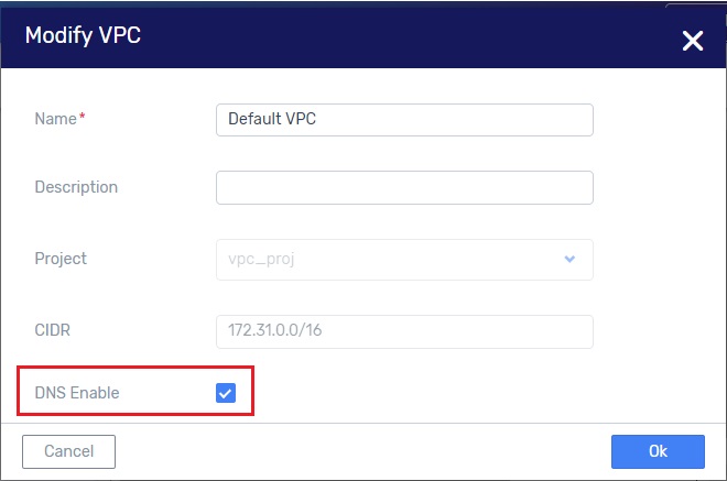
Uncheck the DNS Enable field and click OK .
VPC DNS Enablement or Disablement via the CLI
Use the following command to enable DNS support for a VPC:
vpc update --enable-dns-support true vpc_id
Use the following command to disable DNS support for a VPC:
vpc update --enable-dns-support false vpc_id
Upgrade
For VPCs which were created before enabling the Coredns engine, but were not DNS-enabled, select the VPC on the Networking > VPCs view and click Modify. Then check the DNS Enable field and click OK.
VPCs which were created before enabling the Coredns engine, and are DNS-enabled must be first disabled and then enabled, as follows:
Select the VPC on the Networking > VPCs view and click Modify. Then uncheck the DNS Enable field and click OK. This detaches the VPC from the VPC_DNS engine.
Re-open the Modify PC dialog and check the DNS Enable field. This enables the DNS services for this VPC through the Coredns engine.
To list the DNS engine for each VPC, enter the following command from the CLI:
vpc list -c id -c name -c service_vms
The ‘service_vms’ field will be empty if there is no DNS service. If there is a DNS service the ‘sevice_vms/vm_type’ field will display either ‘dnsmsq’ for the older VPC_DNS engine, or ‘coredns’ for the new DNS engine.
Sample Terraform Scenario
The following scenario describes how you might use VPC DNS support with Terraform.
Enable the VPC engine for your Zadara region (Menu > Networking > Engines > toggle the VPC_DNS Enabled button to ON).
In the Terraform script, set the
enable_dns_supportflag to true, for a specific VPC.
With DNS support enabled, any VM that you create within this VPC can use the private_dns_name returned in the describeInstances response to access other VMs in the VPC.
Here is how this can work:
By default, when DNS support is enabled in a VPC, the system creates a VM with the following host name:
host-a-b-c-d (where a.b.c.d is the VM IP address in the VPC)
So any VM within this VPC can do something like:
“ping host-a-b-c-d” instead of “ping a.b.c.d” and it will work.
This functionality is useful for applications that require DNS names and do not work with IP addresses.
In addition, you can also add DNS A records to external IPs so they will be resolved within this VPC.
For example, you can add an A record to resolve “service.<vpc-domain>” to any IP (usually external to the VPC). This lets you define a globally named services resolution that resides external to the VPC.
This DNS A record feature is useful for the same reason mentioned above – some applications require DNS names and do not work with IP addresses.
NAT Gateways
Introduction to NAT Gateways
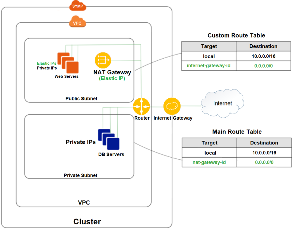
A network address translation (NAT) gateway enables instances in a private subnet to connect to the internet via an elastic IP address, as demonstrated in the diagram below:
Creating a NAT Gateway
Specify the public subnet in which the NAT gateway will reside.
Specify an Elastic IP addresshttps://docs.aws.amazon.com/vpc/latest/userguide/vpc-eips.html with which to associate the NAT gateway once created.
After creation of the NAT gateway, update the route table associated with at least one of your private subnets to direct Internet-bound traffic towards the NAT gateway.
The instances in your private subnets will now be able to communicate with the internet.
Sample NAT Gateway Configuration Flow
(all views are in Region Services, Networking > VPCs)
Initialize the NAT-Gateway service.
In the Networking > NAT Gateways view, click on Initialize.

Verify that you are working on a VPC-enabled project.
In this VPC-enabled project, create a VPC with an internet-gateway
In the Networking > VPCs view, click on Create. This pops-up the Create VPC
If there is no Internet Gateway create one with the +
Create two subnets in the VPC, one called Public and the other called Private.
In the Networking > Subnets view, click on Create. This pops-up the Create Subnet
Create a Subnet called ‘public’.
Pop-up the Create Subnet dialog again.

This time, create a Subnet called ‘private’.
Create two route tables in the VPC, one called public and the other called private.
In the Networking > Route Tables view, click on Create. This pops-up the Create Route Table
Create a Route Table called “public”.
Pop-up the Create Route Table dialog again.
This time create a Route Table called ‘private’.
Associate the public subnet to the public route table, and the private subnet to the private route table.
In the Networking > Route Tables view, click on the public route table. This displays detailed information for the public route table.
In the Subnet Associations tab click on Associate. This pops-up the Associate Subnet dialog.

Associate the public subnet to the public route table.
In the Networking > Route Tables view, click on the private route table. This displays detailed information for the private route table.
In the Subnet Associations tab click on Associate. This pops-up the Associate Subnet dialog.

Associate the private subnet to the private route table.
In the public route table create a default route with the VPC Internet Gateway as the target.
In the Networking > Route Tables view, click on the public route table.
In the Routes tab click on Create. This pops-up the Create Route dialog.

Create a NAT gateway on the public subnet and allocate an elastic IP to it. Wait for the NAT GW state to move from pending to available.
In the Networking > NAT Gateways view, click on Create. This pops-up the Create NAT Gateway dialog.

If there is no Elastic IP available, create one with the ‘+’ button.
In the private route table create a default route with the created NAT Gateway as the target.
In the Networking > Route Tables view, click on the private route table.
In the Routes tab click on Create. This pops-up the Create Route dialog.

Create a VM on the private subnet
In the Compute > Instances, click on Create. This pops-up the Create VM wizard.

Use the private subnet which you created as its network.
You can now connect the VM to the internet via the NAT Gateway Elastic IP.

View the Network Topology diagram of the NAT Gateway in a VPC

In the Networking > Overview screen see the VPC view (but not the Legacy view) of the Network Topology. Note: The red Subnet and VPC frames and labels were drawn in and are not part of the Zadara Cloud Services Network Topology diagram.
Testing Subnet Connectivity
To test the connectivity between a VPC Subnet and a specific IP address.
Using the GUI
In the Networking > Subnets view for a given subnet, click on the Test Connectivity button.
 This pops up the Test Connectivity of Subnet dialog for the given subnet.

Enter a Destination IP address
Select ping or arping. Remember: Ping, which checks Layer 3 connectivity, is blocked by security-group filtering. Arping, which checks Layer 2 connectivity, bypasses security-group filtering.
Click OK.
A notice pops up informing you that the connectivity test is taking place.
A few seconds later, another notice pops up with a status report of the test whether it succeeded or failed, together with relevant connectivity test details. This status report is also available in the right-hand sidebar.
Using the CLI
The ‘guestnet-admin-tool ping-ip create’ command with which you can test a subnet’s connectivity requires the ID of the given subnet (see ‘entity_id’ below). Note: ’–command-type’ is either ‘ping’ (default) or ‘arping’
guestnet-admin-tool ping-ip create [-h]
                                   [-f {adaptive_table,json,shell,table,value,yaml}]
                                   [-c COLUMN] [--max-width <integer>]
                                   [--noindent] [--prefix PREFIX]
                                   [-m [NAME=VALUE [NAME=VALUE ...]]]
                                   [--command-type COMMAND_TYPE]
                                   [--name NAME]
                                   entity_id dest_ip
Run the ‘vpc network list’ command to locate the ID of Subnet-1.
vpc network list -c id -c name
This returns a list of subnets and their IDs.
+--------------------------------------+-----------------------------------------------------+
| id                                   | name                                                |
+======================================+=====================================================+
| ceff2b60-fb75-44d0-8b1a-ac4034b260dc | Subnet-1                                            |
+--------------------------------------+-----------------------------------------------------+
Test the connectivity of Subnet-1 to the destination IP address 8.8.8.8.
guestnet-admin-tool ping-ip create ceff2b60-fb75-44d0-8b1a-ac4034b260dc 8.8.8.8
This returns a temporary, pending status of the subnet’s connectivity, together with the ID of the ping_ip.
+--------------+--------------------------------------+
| id           | 2ce18cc5-b1a8-401c-ae98-99e484f99b3e |
| name         | none                                 |
| status       | pending                              |
| command_type | ping                                 |
| created_at   | 2019-05-12T13:39:56.650560           |
| dest_ip      | 8.8.8.8                              |
| entity_id    | ceff2b60-fb75-44d0-8b1a-ac4034b260dc |
| output       | -                                    |
| project_id   | 07650a05e9dd47c8a3b874a2132e178c     |
| updated_at   | 2019-05-12T13:39:56.650581           |
| user_id      | admin                                |
+--------------+--------------------------------------+
Wait a few seconds and then request the final status of Router-1’s connectivity test by using the ‘guestnet-admin-tool ping-ip get ping_ip_id’, as follows:
guestnet-admin-tool ping-ip get 2ce18cc5-b1a8-401c-ae98-99e484f99b3e
This returns the final, succeeded/failed status of Router-1’s connectivity test with relevant output details.
+--------------+----------------------------------------------------------------+
| id           | 2ce18cc5-b1a8-401c-ae98-99e484f99b3e                           |
| name         | none                                                           |
| status       | succeeded                                                      |
| command_type | ping                                                           |
| created_at   | 2019-05-12T13:39:56                                            |
| dest_ip      | 8.8.8.8                                                        |
| entity_id    | ceff2b60-fb75-44d0-8b1a-ac4034b260dc                           |
|              +----------------------------------------------------------------+
| output       | PING 8.8.8.8 (8.8.8.8) 56(84) bytes of data.                   |
|              | 64 bytes from 8.8.8.8: icmp_seq=1 ttl=118 time=55.1 ms         |
|              | 64 bytes from 8.8.8.8: icmp_seq=2 ttl=118 time=53.3 ms         |
|              |                                                                |
|              | --- 8.8.8.8 ping statistics ---                                |
|              | 2 packets transmitted, 2 received, 0% packet loss, time 1001ms |
|              | rtt min/avg/max/mdev = 53.335/54.219/55.104/0.914 ms           |
|              |                                                                |
|              +----------------------------------------------------------------+
| project_id   | 07650a05e9dd47c8a3b874a2132e178c                               |
| updated_at   | 2019-05-12T13:39:59                                            |
| user_id      | admin                                                          |
+--------------+----------------------------------------------------------------+
This information is automatically deleted after approximately one hour.
Additional options for Subnet (VPC) Connectivity Testing
Delete a specific subnet connectivity test
guestnet-admin-tool ping-ip delete ping_ip_id
List all ping_ip requests
guestnet-admin-tool ping-ip list
Testing Route Table Connectivity
To test the connectivity between a VPC Route Table and an IP address
Using the GUI
- In the Networking > Route Tables view for a given route table, click on the Test Connectivity button.

The Test Connectivity dialog box of the Route Table is displayed.

Enter a Destination IP address
Select ping or arping. Remember: Ping, which checks Layer 3 connectivity, is blocked by security-group filtering. Arping, which checks Layer 2 connectivity, bypasses security-group filtering.
Click OK.
A notice pops up informing you that the connectivity test is taking place.
A few seconds later, another notice pops up with a status report of the test whether it succeeded or failed, together with relevant connectivity test details. This status report is also available in the right-hand sidebar.
Using the CLI
The ‘guestnet-admin-tool ping-ip create’ command with which you can test a route table’s connectivity requires the ID of the given route table (see ‘entity_id’ below). Note: ’–command-type’ is either ‘ping’ (default) or ‘arping’
guestnet-admin-tool ping-ip create [-h]
                                   [-f {adaptive_table,json,shell,table,value,yaml}]
                                   [-c COLUMN] [--max-width <integer>]
                                   [--noindent] [--prefix PREFIX]
                                   [-m [NAME=VALUE [NAME=VALUE ...]]]
                                   [--command-type COMMAND_TYPE]
                                   [--name NAME]
                                   entity_id dest_ip
Run the ‘vpc route-table list’ command to locate the ID of Route Table-1.
vpc route-table list -c id -c name
This returns a list of route tables and their IDs.
+--------------------------------------+-----------------------------------------------------+
| id                                   | name                                                |
+======================================+=====================================================+
| 2fd55d1e-60b3-4887-b376-204b63ce2fa8 | Route Table-1                                       |
+--------------------------------------+-----------------------------------------------------+
Test the connectivity of Route Table-1 to the destination IP address 8.8.8.8
guestnet-admin-tool ping-ip create 2fd55d1e-60b3-4887-b376-204b63ce2fa 8 8.8.8.8
This returns a temporary, pending status of the route table’s connectivity, together with the id of the ping_ip.
+--------------+--------------------------------------+
| id           | ab1e76df-4531-42db-a455-02a402e70ae5 |
| name         | none                                 |
| status       | pending                              |
| command_type | ping                                 |
| created_at   | 2019-05-12T14:15:11.379402           |
| dest_ip      | 8.8.8.8                              |
| entity_id    | 2fd55d1e-60b3-4887-b376-204b63ce2fa8 |
| output       | -                                    |
| project_id   | 07650a05e9dd47c8a3b874a2132e178c     |
| updated_at   | 2019-05-12T14:15:11.379416           |
| user_id      | admin                                |
+--------------+--------------------------------------+
Wait a few seconds and then request the final status of Route Table-1’s connectivity test by using the ‘guestnet-admin-tool ping-ip get ping_ip_id‘.
guestnet-admin-tool ping-ip get ab1e76df-4531-42db-a455-02a402e70ae5
This returns the final, succeeded/failed status of Route Table-1’s connectivity test with relevant output details.
+--------------+------------------------------------------+
| id           | ab1e76df-4531-42db-a455-02a402e70ae5     |
| name         | none                                     |
| status       | failed                                   |
| command_type | ping                                     |
| created_at   | 2019-05-12T14:15:11                      |
| dest_ip      | 8.8.8.8                                  |
| entity_id    | 2fd55d1e-60b3-4887-b376-204b63ce2fa8     |
|              +------------------------------------------+
| output       |  ; error=connect: Network is unreachable |
|              |  ; status=2                              |
|              +------------------------------------------+
| project_id   | 07650a05e9dd47c8a3b874a2132e178c         |
| updated_at   | 2019-05-12T14:15:12                      |
| user_id      | admin                                    |
+--------------+------------------------------------------+
This information is automatically deleted after approximately one hour.
Additional Commands for Route Table (VPC) Connectivity Testing
Delete a specific route table connectivity test
guestnet-admin-tool ping-ip delete ping_ip_id
List all ping_ip requests
guestnet-admin-tool ping-ip list