Getting Started
This chapter contains step-by-step instructions to create a VPSA and then to configure its storage properties.
Registering a Zadara Account & Creating a VPSA
Go to your organizational/cloud service provider VPSA Provisioning Portal
Click on Create account for first time user registration
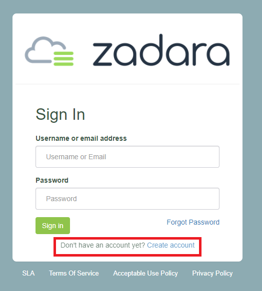
Complete the form to create a Zadara Account.
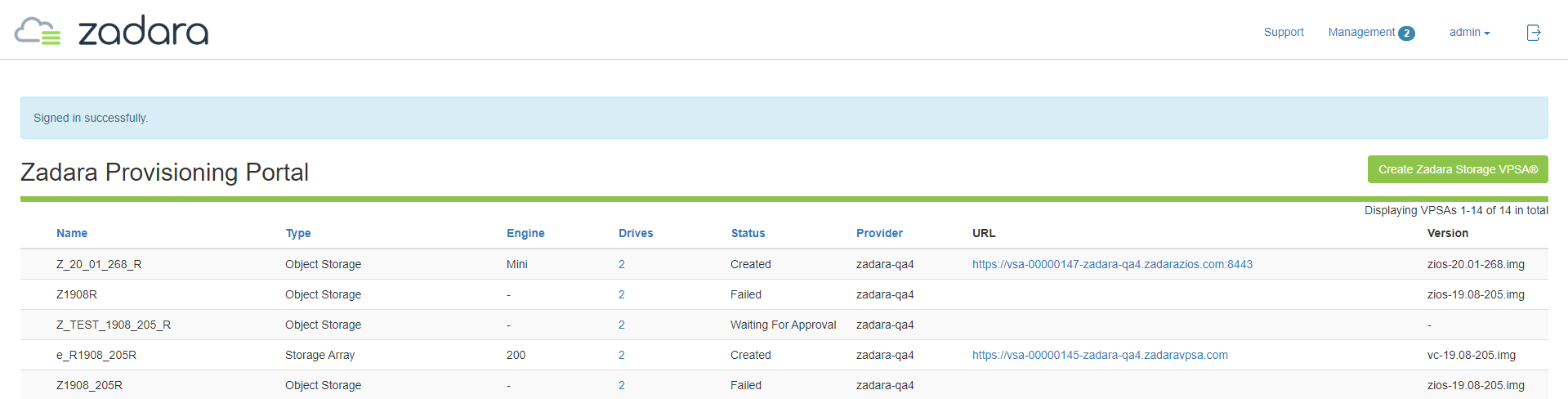
go to your VPSA Provisioning Portal.
Login using your username / email and password, then press Create Zadara Storage VPSA® to create a new VPSA.
Note
Zadara has a public cloud Provisioning portal. User registration can be performed at: https://manage.zadarastorage.com/register/ .
The following dialog will appear:
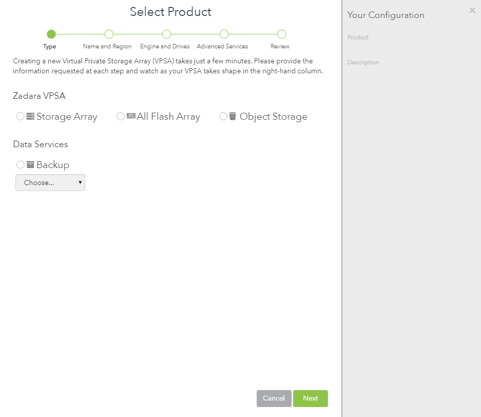
Select either Storage Array to create a hybrid storage array or Flash Array to create a performance optimized flash array with built in inline data reduction support.
Note
VPSA Object Storage (ZIOS) creation is described in the VPSA Object Storage User Guide.
The VPSA definitions dialog will appear
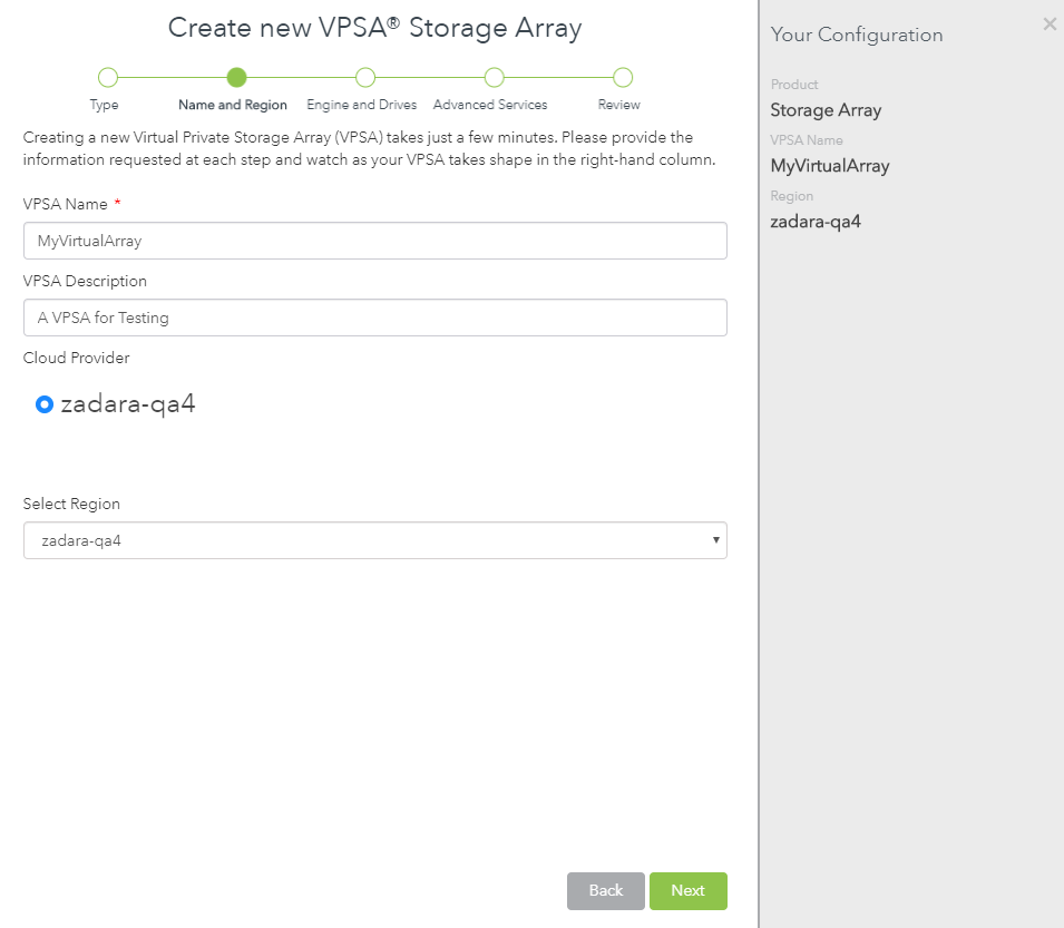
Enter the following mandatory fields:
VPSA Name – Give the VPSA a name. This is how it will appear in the Cloud Console and in the VPSA GUI. If you are planning on having multiple VPSAs, you might want to give it as detailed a name as possible.
VPSA Description – Give the VPSA a description.
Select Cloud Provider – Select the Cloud or Co-lo where you have your compute instances. VPSAs are able to simultaneously connect to multiple Cloud Providers and Co-locations (within the same geographical region).
Note
From the public cloud Provisioning Portal you can provision and manage all of your VPSAs, even if they are connected to different Cloud Providers & regions.
Select a Region – Select the Cloud Provider region where your application servers reside. The servers and the VPSA must reside in the same region in order to establish efficient iSCSI or NFS\CIFS connectivity. Available Regions depend on which Cloud Provider you select.
Protection Zone – VPSA supports multiple protection zones in “stretched cluster” configurations, where each VC is in a different zone. In cloud locations that provide protection zones, select in which zone the new VPSA will be built. For multi-zone configurations select Multiple.
Click Next
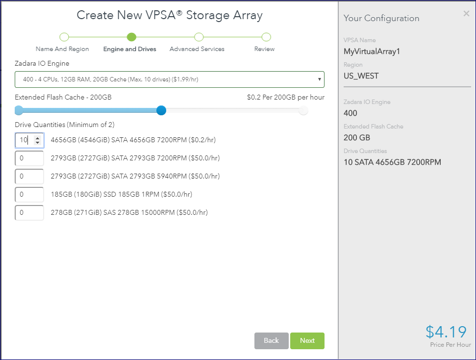
Select the Zadara IO Engine – The Zadara IO Engine type defines the compute characteristics of your VPSA’s Virtual Controllers (VCs). Each engine type defines the following characteristics:
Number of CPUs that are assigned to your VPSA’s VCs.
Amount of RAM that is assigned to your VPSA’s VCs.
 Default size of protected SSD Cache.
When selecting the IO engine, take into account the capacity planned for this VPSA. Each Engine has a limit to the number of drive it can support, and to the total raw capacity of the VPSA.
You can change the Zadara Engine type (upgrade or downgrade) at any time throughout the lifetime of your VPSA according to your application’s needs,providing you stay within the maximum limits of the engine type you are moving to
Note
The compute resources (CPU, RAM and Cache) are dedicated to your VPSA, which ensures consistent performance and isolation from other tenants’ workloads and behavior.
-
Select the Cache size (for Storage Array engines larger than 200)
Use the slide bar to set the amount of flash cache allocated to this
VPSA. Note that each VPSA engine comes with a minimum amount of
cache. The extended cache is allocated in 200GB increments.
Drive Quantities – Select the type and number of drives that you would like allocated to your VPSA.
The Zadara Cloud Orchestrator allocates dedicated drives.
Drives are allocated from as many different SNs as possible to provide max redundancy for your VPSA’s RAID groups.
There is a limit to the number of drives per Zadara IO Engine type. The larger the Engine is, the more drives you can add. There is also a limit to the total raw capacity of all drives. Make sure the total capacity of all selected drives is within the limit.
The following table lists the maximum drives per Storage Array Engine type:IO Engine Type
Maximum # of Drives
Maximum Raw Capacity
200 (Baby)
5
24 TB
400 (Basic)
10
70 TB
600 (Boost)
20
140 TB
800 (Blast)
30
180 TB
1000 (Blazing)
40
240 TB
1200
60
300 TB
1600
80
400 TB
2400
80
800 TB
3600
80
1000 TB
 The following table lists the maximum drives and capacity per All Flash Array Engine type:
Note that for All Flash Array, due to data reduction, the capacity limit per engine depends on both the
physical capacity of the drives and the the customer virtual capacity (as seen by the hosts),
before any data reduction. More about All Flash Array capacities: Understanding Pool’s Capacity
The following table lists the maximum drives and capacity per All Flash Array Engine type:
Note that for All Flash Array, due to data reduction, the capacity limit per engine depends on both the
physical capacity of the drives and the the customer virtual capacity (as seen by the hosts),
before any data reduction. More about All Flash Array capacities: Understanding Pool’s CapacityIO Engine Type
Maximum # of Drives
Maximum Raw Capacity
Maximum Customer (host) Capacity
H100
60
280 TB
140 TB
H200
80
440 TB
220 TB
H300
120
800 TB
400 TB
H400
140
1000 TB
50 0 TB
Note
The above capacities depend on the type of the pool(s) used. The numbers shown are the limits of the aggregated size of all pools of type Throughput Optimized. See Creating a Pool for details
Click Next
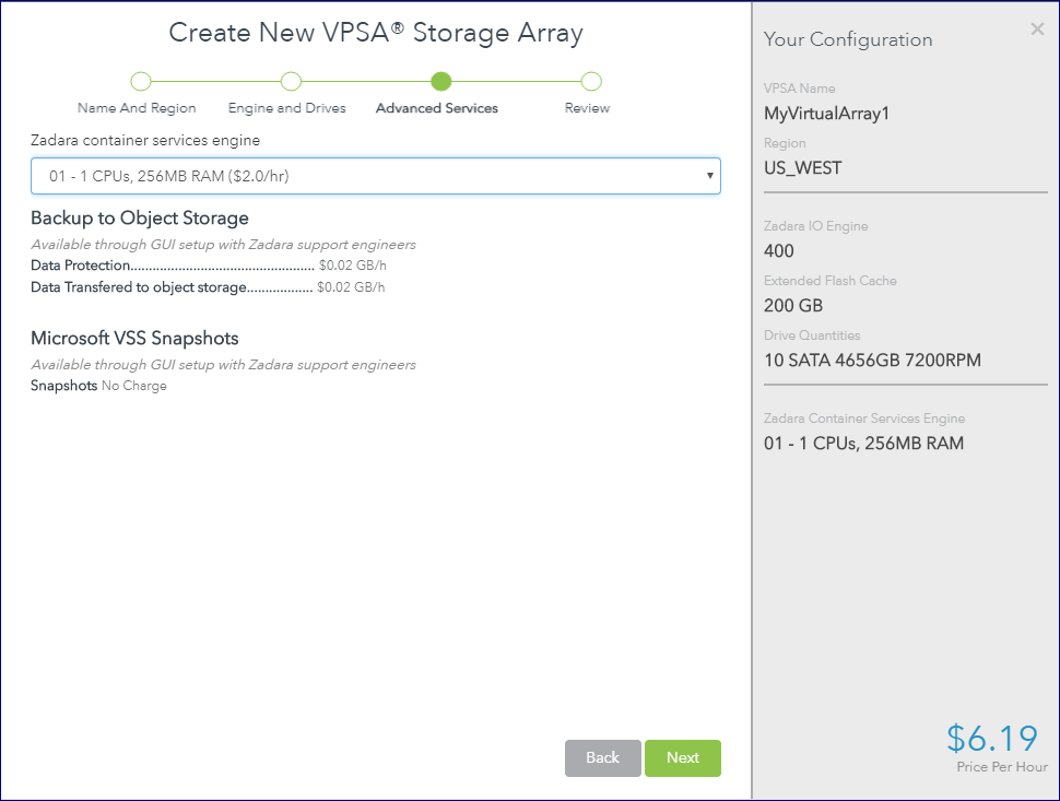
Select the Zadara Container Services (ZCS) Engine – The Zadara ZCS Engine defines the compute resources of the VPSA’s Virtual Controllers that are allocated for Docker containers within this VPSA. Refer to Managing Container Services for details about Zadara Container Services.
Fibre Channel Support – Check this checkbox if you will be connecting hosts to this VPSA over FC SAN.
Click Next
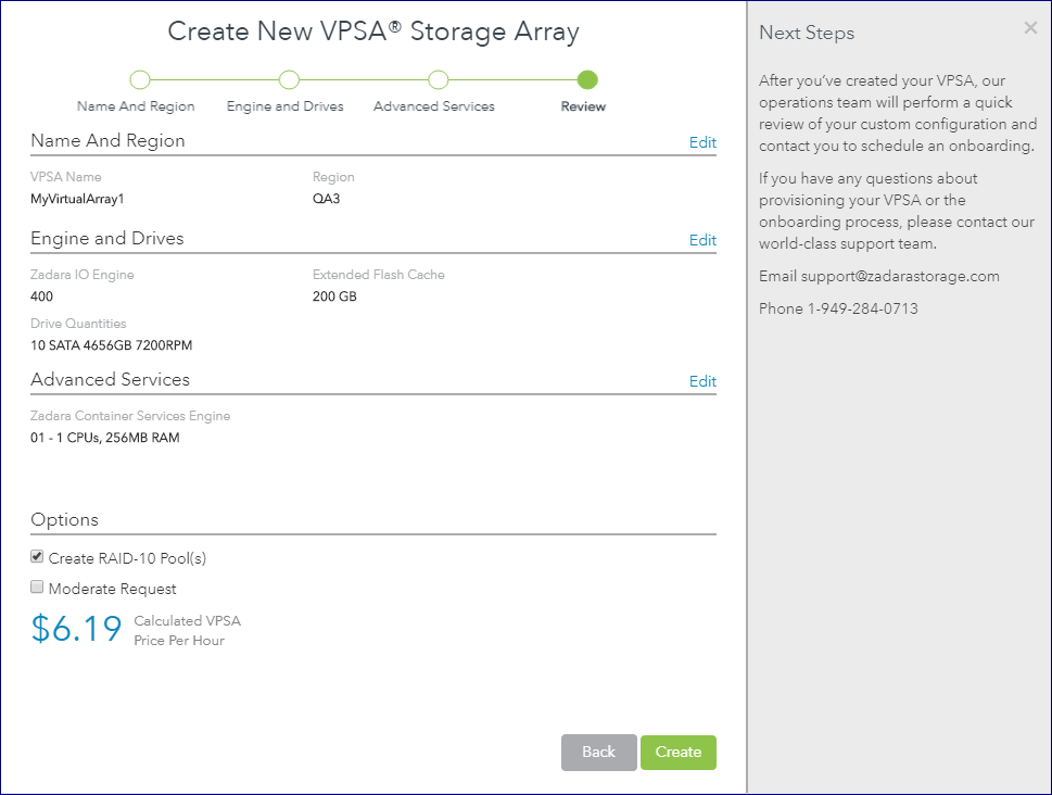
Create RAID-10 Pool(s) – By default, at VPSA creation time RAID-10 pools are automatically created. One pool per each drives type selected. All the drives selected Of each type will be included in the pool. If you want to create different pools setting, uncheck this checkbox, and manually create your RAID groups and pools as described below.
Once you have completed selecting the above VPSA characteristics, review the displayed summary. You can click Edit to modify your previous selections. Press the Create button to confirm the VPSA creation request. The requested VPSA will appear in the “Awaiting Approval” list.
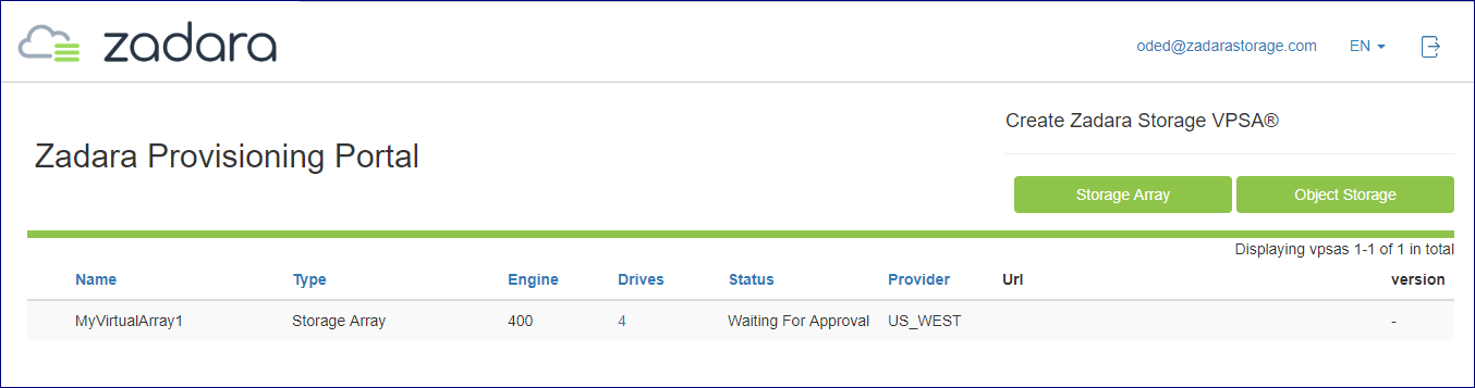
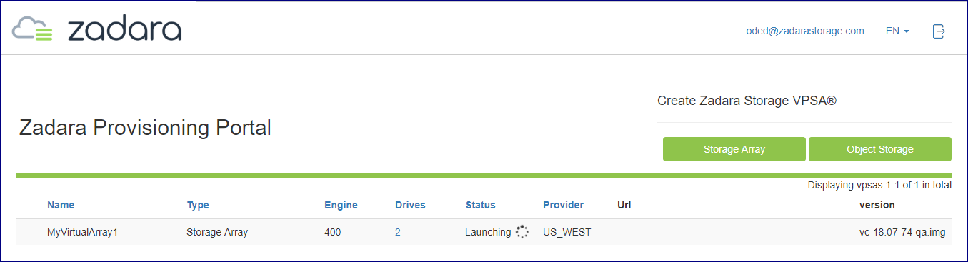
Completing the VPSA creation requires the approval of a Zadara Storage Cloud admin. Once approved, the new VPSA only takes a few minutes to launch. During that time you’ll see your VPSA in “Launching” status as shown below:
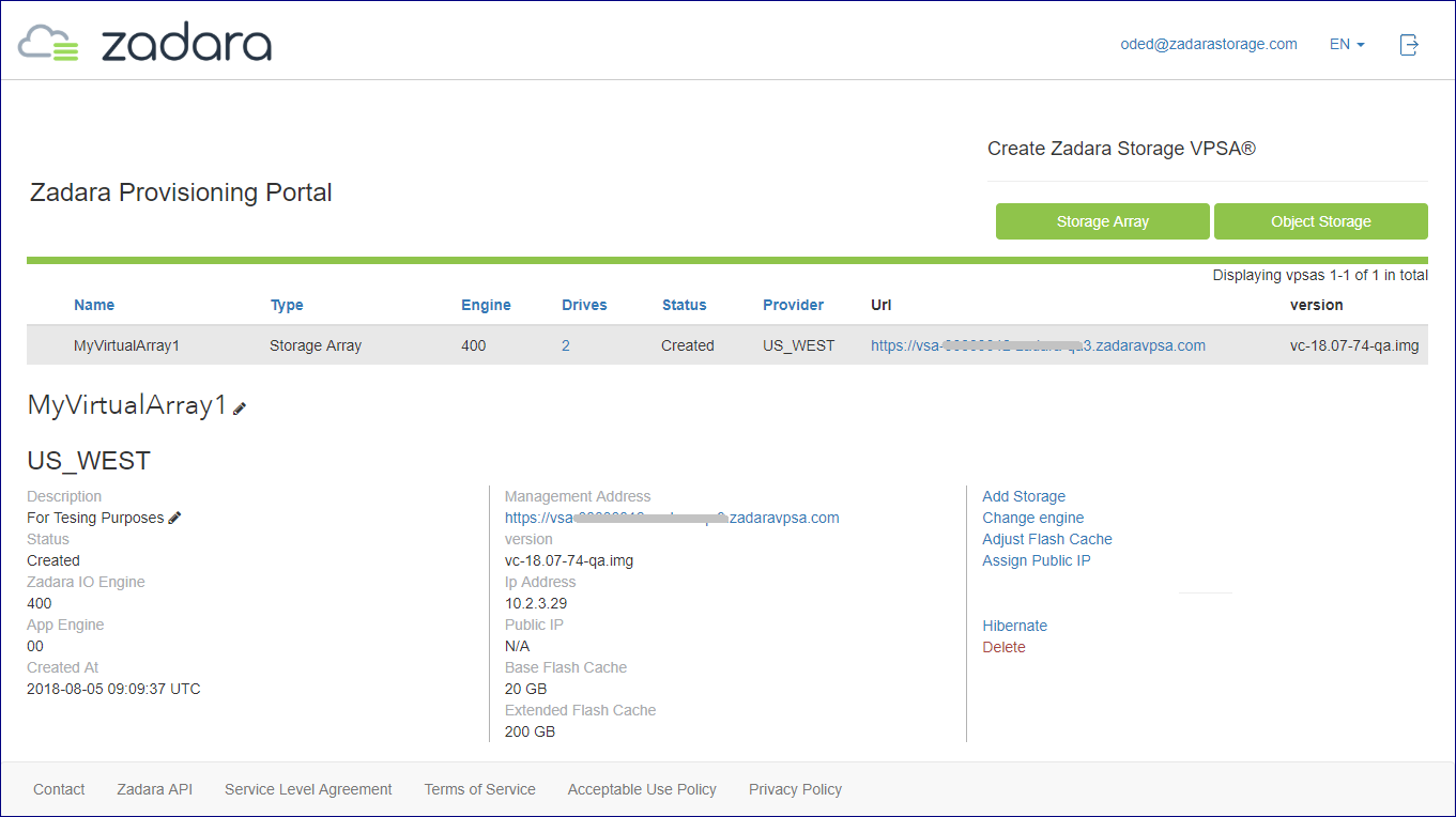
Once the VPSA is ready, you’ll receive an email with a temporary passcode at your registered email address.
Use the “Management Address” link to access the VPSA GUI:
Use your registered username or email address and the temporary passcode to enter the VPSA GUI. You will be immediately prompted to set a new password for your VPSA User account.
The VPSA Interface
Note
The VPSA management interface web application is supported in all modern browsers. We recommend using Google Chrome, Firefox or Microsoft Edge for an optimal user experience.
Understanding the VPSA Dashboard
VPSA Dashboard is the landing page, every time the GUI opens. It gives the overall state of the VPSA (Health, Capacity, Performance) at a glance. The Dashboard is made of the following components:
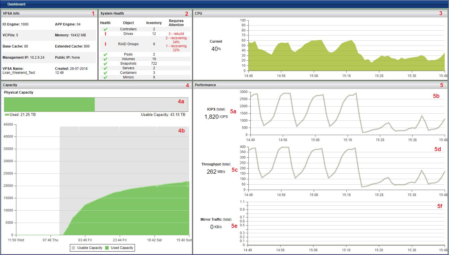
VPSA Info: General information of the VPSA such as name, engine type and management IP Address.
System Health: Shows the inventory of the objects managed by the system, such as Pools, Volumes, Mirrors etc… If all objects are in “normal” state, there is a green checkmark on the line. If there is situation that needs your attention a red exclamation mark is shown on that specific line, with number of objects that need to be taken care of.
CPU: Shows the CPU utilization of the active Controller of the VPSA, over time. This chart gives an indication of the load on the storage system.
Capacity: Shows the capacity state of the VPSA. The display is different between Storage Array and All Flash Array. For the later it shows the capacity reduction saving. See Understanding Pool’s Capacity for details.
Current capacity state
Capacity consumption over time during the last month
Performance: These charts show the aggregated performance of all Volumes.
Current IOPS (reads and writes) of all Volumes
IOPS activity during the last hour
Current throughput of all Volumes
Throughput of all volumes during the last hour
Current mirroring traffic of all mirrors (outbound and inbound)
Mirroring activity of all mirrors during the last hour
Understanding the VPSA GUI
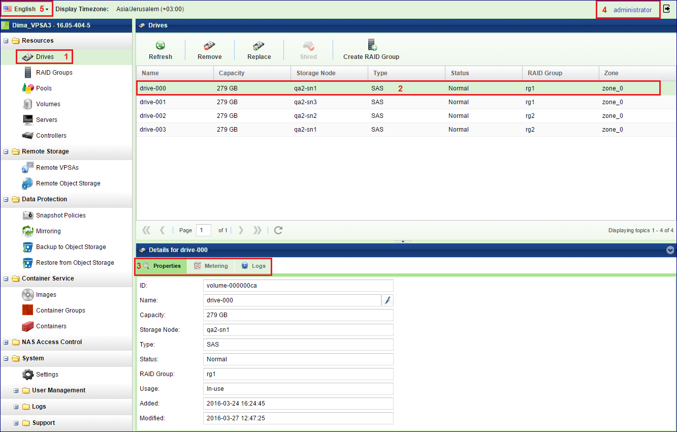
The VPSA GUI provides full management and control of your VPSA. It contains the following main components (as numbered in the above screenshot):
Main Navigation Left Panel – Traverse through the various VPSA entities. The selected entity is highlighted.
The Center Pane – Displays a list of objects from the selected entity type (e.g. Drives in the above screenshot example) and for each object it displays the main properties.
The South Pane – Displays detailed information regarding the selected object. All objects have at least 3 tabs:
Properties – Detailed properties of the object.
Metering – Typically IO workload metering info.
Logs – List of event-log messages related to that object.
Logged-in username – Displayed at the top right corner.
Selected Language – Displayed at the top left corner. You can use this drop down to change the displayed language.
Note
Creating RAID Group, Pools, and Volumes
By default a new VPSA is created with all its drives configured in RAID Groups, and a Pool per each drives type. If the automatic pools satisfy your needs go directly to the volumes creation below. Otherwise follow the RAID Group and Pool creation instruction.
Create a RAID Group to define the level of data protection needed. For more details see here: Creating a RAID Group
Create a storage Pool by using aggregated capacity from one or more RAID Groups. For more details see here: Creating a Pool
Create an iSCSI\FC\NFS\SMB Thin Provisioned Volume to be used by your servers. For more details check here: Creating and Deleting a Volume
Add a server. The server object represents the host using the storage volume. Follow the instructions depending on OS and connectivity of your server: Adding a Server
Attach the Volume to a Server. For more details see here: Attaching & detaching Volumes to Servers
Congratulations! You have a new VPSA provisioned and ready to use.
<table border=”1” class=”docutils”> <thead> <tr> <th></th> </tr> </thead> <tbody> <tr> <td></td> </tr> </tbody> </table>
The following sections describe in detail the various capabilities and services of your VPSA.
Provisioning your VPSA
You create, add, change, delete and manage the resources composing your VPSAs via the Zadara Provisioning Portal.
This section describes the available operations in the Provisioning Portal (https://manage.zadarastorage.com).
Adding and removing Disk Drives
To add drives to your VPSA go to the Provisioning Portal, select the VPSA and then press the Add Storage button.
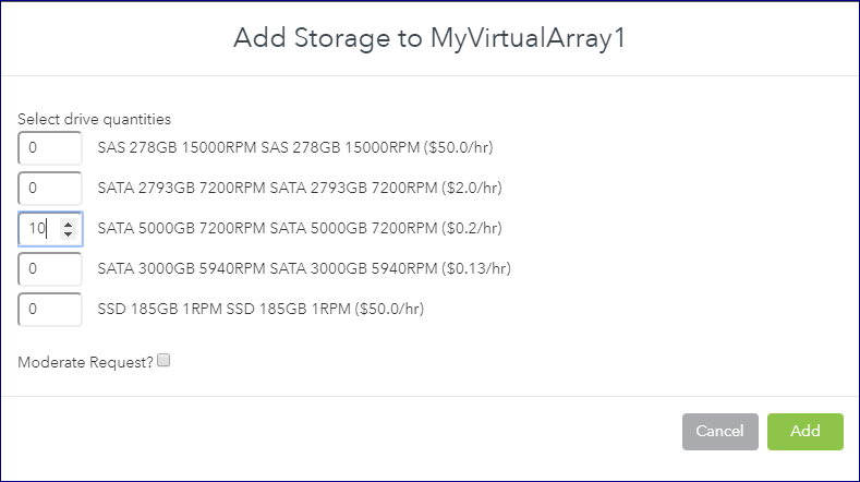
Select the number of drives from each available drive type you wish to add to your VPSA, and press Submit. Keep in mind the RAID Groups you are going to build.
This operation requires the approval of a Zadara Storage Cloud Admin. Once approved, you’ll see the number of drives in the Provisioning Portal update accordingly. If you then refresh the Drives page in the VPSA GUI the new drives will be displayed.
You can remove unused Drives (indicated with status “Available”) from within the VPSA.
Go to the , select the Drive you wish to remove and press the Remove button:
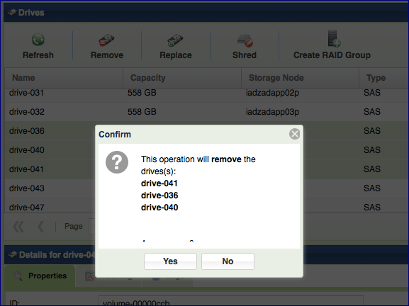
If you wish to remove a Drive that is part of a RAID Group you first need to replace it with another Drive as described here: Replacing a Drive
Managing Zadara Engines
The Zadara IO Engine type defines the following characteristics of your VPSA’s Storage Controllers:
Dedicated CPU and memory resources - These are dedicated solely to your VPSA. These resources are not shared with any other VPSA or tenant within the Zadara Storage Cloud.
- Flash Cache Size - Each VPSA is provisioned with a Flash Cache
partition to be used for both metadata and read/write caching. The
SSD cache partition is protected using RAID-1, where each mirror copy
resides on a different SN, thus ensuring cache resilience to SN
failure. Each Engine type comes with a base SSD cache partition size.
You can request additional flash capacity for caching. For more
details see “Adjusting Cache.”
Maximum number of drives – The maximum number of drives that can be allocated to each VPSA engine type.
The following Zadara IO Engines are available For Storage Array:
IO Engine Type |
Dedicated Compute Resources |
Base Flash Cache |
Max # of Drives |
Max Raw Capacity |
|---|---|---|---|---|
200 (Baby) |
2 CPU, 6 GB RAM |
20 GB |
5 |
24 TB |
400 (Basic) |
4 CPU, 12 GB RAM |
20 GB |
10 |
70 TB |
600 (Boost) |
6 CPU, 20 GB RAM |
40 GB |
20 |
140 TB |
800 (Blast) |
8 CPU, 28 GB RAM |
60 GB |
30 |
180 TB |
1000 (Blazing) |
10 CPU, 36 GB RAM |
80 GB |
40 |
240 TB |
1200 |
12 CPU, 52 GB RAM |
100 GB |
60 |
300 TB |
1600 |
16 CPU, 68 GB RAM |
120 GB |
80 |
400 TB |
2400 |
24 CPU, 100 GB RAM |
180 GB |
80 |
800 TB |
3600 |
36 CPU, 144 GB RAM |
240 GB |
80 |
1000 TB |
The following Zadara IO Engines are available For All Flash Array:
Note that for All Flash Array, due to data reduction, the capacity limit per engine depends on both the
physical capacity of the drives and the the customer virtual capacity (as seen by the hosts),
before any data reduction. More about All Flash Array capacities: Understanding Pool’s Capacity
IO Engine Type |
Dedicated Compute Resources |
Maximum # of Drives |
Maximum Raw Capacity |
Maximum Customer (Host) Capacity |
|---|---|---|---|---|
H100 |
12 CPU, 72 GB RAM |
60 |
280 |
140 TB |
H200 |
24 CPU, 116 GB RAM |
80 |
440 |
220 TB |
H300 |
36 CPU, 176 GB RAM |
120 |
800 |
400 TB |
H400 |
48 CPU, 236 GB RAM |
140 |
1000 |
500 TB |
Note
The above capacities depend on the type of the pool(s) used. The numbers shown are the limits of the aggregated size of all pools of type Throughput Optimized. See Creating a Pool for details
The following Zadara Container Services Engines (see: Managing Container Services) are available:
Zadara ZCS Engine Type |
Dedicated compute resources |
|---|---|
01 |
2 CPU, 512 MB RAM |
02 |
2 CPU, 1 GB RAM |
04 |
4 CPU, 2 GB RAM |
06 |
6 CPU, 4 GB RAM |
08 |
8 CPU, 8 GB RAM |
To change both types of Zadara Engines, press the Change Engine link in the Zadara Provisioning Portal:
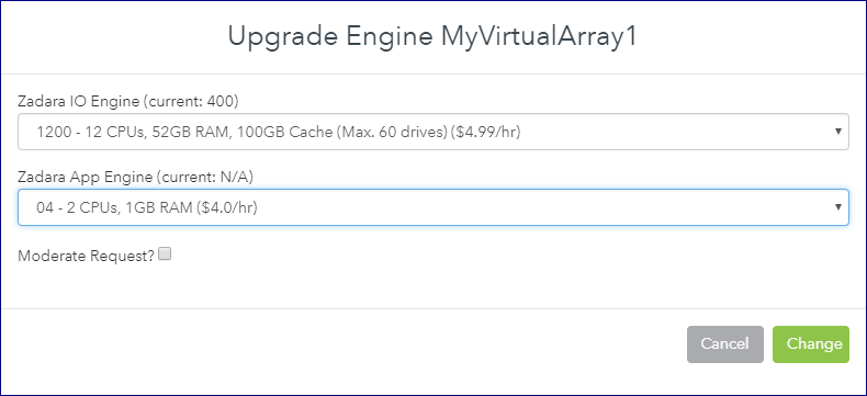
When selecting any engine larger than 200 you can also select the required flash cache size for that engine. For Flash Cache limits see here.
Completing this operation requires the approval of the Zadara Storage Cloud Admin.
The Zadara Engine upgrade/downgrade process may take a few minutes. During that time, your VPSA status will change to “Upgrade Pending”.
When the process completes the VPSA status will change back to “Ready”.
Managing Virtual Networks
The Zadara cloud provides a flexible and dynamic virtual networking infrastructure that can be tailored to meet multiple storage architecture and use cases.
Each cloud tennant is allocated with one or more “Virutal Networks” which is a set of available IP addresses within a specific network segment. Virtual networks are allocated for a specific cloud tenneant and within a specific avilable cloud VLAN.
The below diagram depicts the relationship between cloud tenants, virtual networks and VLANs:
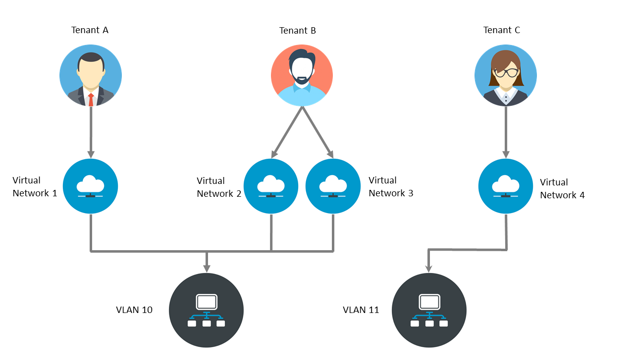
In case a VPSA serves as storage for servers on different networks, the VPSA can be plugged on multiple “Virtual Networks”. Both block volumes and NAS shares can simultaneously be exposed through one or more Virtual Networks.
Each VPSA is created with a primary network for its front end (hosts connectivity). This network is routable and is mandatory.
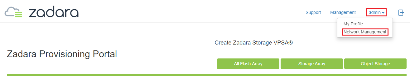
You can manage your virtual networks from the Zadara Provisioning Portal. click Network Management in the Zadara Provisioning Portal’s Management Menu.
To create another virtual network press Create , and fill in the requested parameters such as: CIDR, Gateway, IP Range, and whether IPv4 or IPv6 should be used.
You can add (and remove) secondary networks to the VPSA. The VPSA internally maintains a “Virtual Networks Interface” (VNI) that connects into each virtual networks.
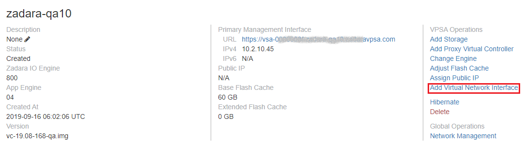
To add Virtual Network Interface, press the Add Virtual Network Interface link in the Zadara Provisioning Portal VPSA Operations.
To remove Virtual Network Interface, press the Remove Virtual Network Interface link in the Zadara Provisioning Portal VPSA Operations.
Note
Number of VNIs per VPSA is limited to 5.
VPSA REST API/GUI is accessible through any VNI.
Only Primary VN IP is registered in DNSimple
VPSA can’t have two VNI with the same VLAN.
Note
Only “Primary Virtual Network” is a routable network. Remaining virtual networks are not routable. There are some limitations on the remaining virtual networks:
Active Directory can be joined only through “primary virtual network”.
Backup (B2OS), Mirror, Remote Clone through FE network are only allowed via the “primary virtual network”.
ZCS container services exposed through FE network can be done only on “primary virtual network”.
“iSER” host connectivity is available only on the “Primary Virtual Network”.
Assigning Public IPs
By default you cannot access the VPSA from the public Internet for security and privacy reasons. The VPSA Front-End IP address which is used for VPSA management (via GUI and REST API) and for data IO workload (host connectivity via iSCSI/NFS/SMB protocols), is allocated on the Zadara Storage Cloud “Front-End” network 10GbE interface which is routable only from the Cloud Servers network. Servers outside of your Cloud Servers network cannot reach this IP address. This means you cannot access your VPSA GUI from the Internet.
A typical use case requiring Public IP addresses is when you’re running Asynchronous Remote Mirroring between two VPSAs in different regions, between on premise and cloud deployments or even between different Cloud Providers for Disaster Recovery (DR). Communication between the VPSAs is done via an authenticated and encrypted channel over the public Internet, thus requiring Public IPs.
To assign a Public IP address to your VPSA, go to the Provisioning Portal and press the Assign Public IP link. You can see the assigned IP address in your VPSA details in the Provisioning Portal and in the VPSA GUI, under . To remove it, simply click the Remove Public IP button in the Provisioning Portal.
Note
Access to the VPSA GUI and API is blocked through the Public IP for security reasons.
Note
NAT’d server IP connections are not supported for iSCSI, NFS, and SMB protocols over the Public IP.
Adjusting Flash Cache
Each VPSA is provisioned with a base flash cache partition, which is utilized by the VPSA for both metadata and read/write caching. The initially assigned default SSD cache size is also the minimal cache size for a given Zadara Engine. The flash cache partition is protected using RAID-1, where each mirror copy resides on a different SN, thus ensuring cache resilience to multiple types of failure.
On top of the base flash cache described above, you can add an extended cache. The VPSA extended flash cache size is elastic, so you can increase or decrease the cache size according to the needs of your workload.
Each Engine type has a minimum (default) and maximum SSD Cache size, as shown in the table below:
Zadara Engine |
Base Flash Cache |
Default Extended Flash Cache Size |
Max Extended Flash Cache Size |
|---|---|---|---|
200 (Baby) |
20 GB |
0 GB |
0 GB |
400 (Basic) |
20 GB |
200 GB |
400 GB |
600 (Boost) |
40 GB |
400 GB |
800 GB |
800 (Blast) |
60 GB |
600 GB |
1200 GB |
1000 (Blazing) |
80 GB |
800 GB |
1600 GB |
1200 |
100 GB |
1200 GB |
2400 GB |
1600 |
120 GB |
1600 GB |
3200 GB |
2400 |
180 GB |
1600 GB |
3200 GB |
3600 |
240 GB |
1600 GB |
3200 GB |
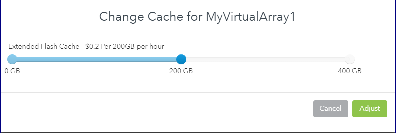
To change the Extended Flash Cache size for your VPSA, go to the Provisioning Portal and press the Adjust Flash Cache link:
Hibernating your VPSA
You can hibernate your VPSA when it is not in use for some period of time in order to reduce its associated service cost. While the VPSA is in a hibernated state you will only be billed for the drives, not the engine. Hibernating a VPSA involves the process of deleting its Virtual Controllers (the VPSA) while maintaining the data drives and all the necessary metadata to resume its operation at a later stage. No data is lost! The hibernated VPSA is not accessible to any GUI or REST API commands, nor will it present any iSCSI or NFS\SMB volumes. Resuming a hibernated VPSA only takes a few minutes.
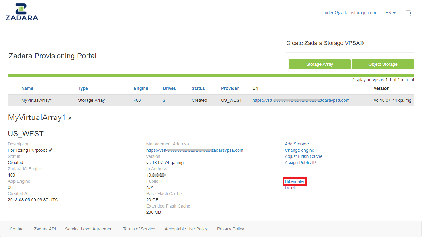
To hibernate a VPSA, go to the VPSA Provisioning Portal and press the Hibernate link:
To resume access to the VPSA, go to the Provisioning Portal and press the Restore link. (The Hibernate and Restore toggle depending on the current state of the VPSA.)