Managing RAID Groups and Drives
Creating a RAID Group

VPSA RAID Groups define the level of protection against disk failure of the Pools and Volumes which contain the user’s data. Careful consideration must be given when selecting the RAID level, along with the number and type of drives, in order to avoid potential impact on performance of your data. RAID groups always span across drives from different Storage Nodes, thus a RAID Group is resilient to both a single drive failure (RAID-6 allows for a 2-drive failure) as well as to a complete Storage Node failure.
To create your RAID Groups first select the Drives entity in the Main Navigation Panel (Left Panel) and then click the Create RAID Group button in the Center Panel.
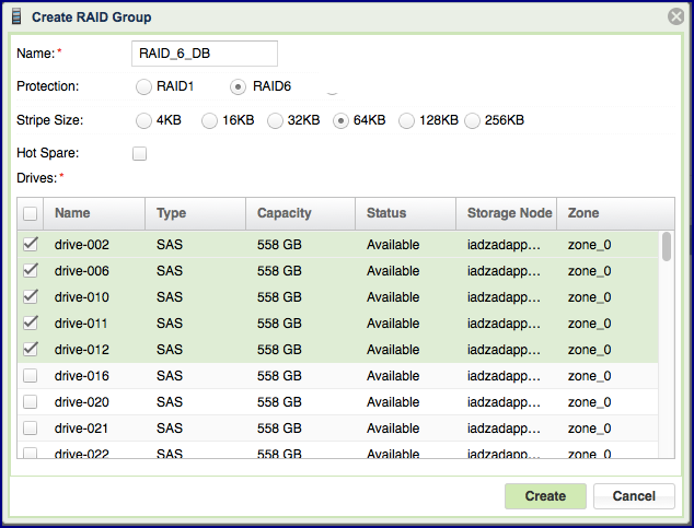
Define the following attributes in the “Create RAID Group” dialog box:
Enter the RAID Group name (you will later add it to a Pool so you may want to provide a meaningful name that describes the target usage of the Pool).
Note
Objects names can be up to 128 chars long and can contain letters and digits, dashes “-” and underscores “_”
Select Protection Type. Refer to the table below for a description of the various RAID levels.
Select Stripe Size. Choosing a Stripe Size other than the default value of 64K is only applicable to RAID-6 and depends on the performance needs specific to your workload.
Select whether to allocate a drive as a Hot Spare for this RAID group. Adding Spare drive for RAID-1 groups is recommended. See more details about managing Hot Spares here.
Select the drives that will participate in the RAID Group. As noted in the table below, for RAID-1 a minimum of 2 drives is required. For RAID-6: in a VPSA Storage Array a minimum of 4 drives is required and a VPSA Flash Array supports 4+2 or 8+2 RAID group configurations.
For maximum redundancy drives MUST be selected from different Storage Nodes so VPSA will prevent you from doing otherwise.
It is possible but not recommended to mix drives of different types in a single RAID Group.
RAID-5 is no longer supported.
Understanding RAID levels
The following RAID level are supported:
RAID level |
Description |
|---|---|
RAID-1 (Mirroring) |
RAID-1 mirrors the contents of one hard drive in the group onto another. If either hard drive fails, the other hard drive takes over and normal system operations are not interrupted. RAID-1, or Drive Mirroring, creates fault tolerance by storing duplicate sets of data on a minimum of two hard drives, and offers an excellent combination of data protection and performance. There must be 2 or 3 drives in a RAID-1 group. RAID-1 and RAID-10 are the most costly fault tolerance methods because they require 50 percent of the total combined drives capacity to store the redundant data. |
RAID-6 |
RAID-6 uses multiple parity sets to store data and can therefore tolerate up to 2 drive failures simultaneously. It requires a minimum of 4 drives. It offers the best data protection. Usable capacity is N-2 where N is the number of physical drives in the logical array. |
RAID-10 (Mirroring and Striping) |
RAID-10, or Drive Mirroring and Striping, is achieved in a VPSA by creating RAID-1 RAID Groups and striping them together at the Pool level. RAID-10 first mirrors each drive in the array to another, and then stripes the data across the mirrored pair. If a physical drive fails the mirror drive takes over and normal system operations are not interrupted. RAID 10 can withstand multiple simultaneous drive failures, as long as the failed drives are not mirrored to each other. RAID-10 creates fault tolerance by storing duplicate sets of data on a minimum of four hard drives and offers the best combination of data protection and performance. RAID-10 is the most costly fault tolerance method because it requires 50 percent of the total combined drives capacity to store the redundant data. |
RAID-60 |
RAID-60 are achieved (similar to RAID-10) by creating RAID-6 RAID Groups and striping them together at the Pool level. |
Viewing RAID Group properties
The RAID-Group’s details (properties and metering), are shown in the South Panel tabs:
Properties
Each RAID Group includes the following properties:
Property |
Description |
|---|---|
ID |
An internally assigned unique ID. |
Name |
User assigned name. Can be modified anytime. |
Comment |
User free text comment. Can be used for labels, reminders or any other purpose |
Protection |
Selected RAID level—RAID-1 or RAID-6. |
Capacity |
Total protected and usable capacity of the RAID Group. |
Available Capacity |
The RAID Group’s usable capacity that is not allocated to any Pool. |
Stripe Size |
Stripe size (per drive) for RAID-6. |
Mirror Number |
Number of mirror copies for RAID-1. |
Protection Width |
Number of Drives participating in a RAID-6 RAID Group (including parity). |
Status |
|
Created |
Date & time when the object was created. |
Modified |
Date & time when the object was last modified. |
Drives
Lists the disk Drives participating in the selected RAID Group. The following information is displayed per drive:
Name
Capacity (in GB)
Location (Storage Node)
Type (SAS/SATA/SSD/TBD)
Status (Normal/Failed/TBD)
Hot Spare (Yes/No)
Metering
The Metering Charts provide live metering of the IO workload associated with the selected RAID Group.
The charts display the metering data as it was captured in the past 20 intervals. An interval length can be one of the following: 1 second, 10 Seconds, 1 minute, 10 minutes, or 1 hour. The Auto button lets you see continuously-updating live metering info.
Note
The metering info of the RAID Group doesn’t include RAID-generated IOs, such as when doing a rebuild.
The following charts are displayed:
Chart |
Description |
|---|---|
IOPs |
The number of read and write commands issued to the RAID Group per second. |
Bandwidth (MB\s) |
Total throughput (in MB) of read and write SCSI commands issued to the RAID Group per second. |
IO Time (ms) |
Average response time of all read and write SCSI commands issued to the RAID Group per selected interval. |
Logs
Displays all event logs associated with this RAID Group.
Understanding Hot Spare Drives

When creating a RAID Group you can decide whether you’d like to allocate hot spare drives to the RAID Group or not. You can change this selection at any time by clicking the Add Spare or Remove Spare buttons on a selected RAID Group in the VPSA GUI > RAID Groups page.
Allocating a hot spare drive for a RAID Group allows for immediate and automated drive replacement, with no human intervention, once the VPSA determines that the drive has failed.
If you choose not to allocate a hot spare drive to your RAID group, you can still replace a failed drive with any available drive that is not used in any other RAID Group within the VPSA. You can execute this process manually, or automate it via the VPSA REST APIs. Simply identify and select the failed drive, click the Replace button and select the available drive to use for the replacement. For more details see here: Replacing a Drive.
Managing RAID Group Sync Speed
RAID Group Sync Speed allows you to control the rate with which data is synchronized during a RAID rebuild process on both a newly created RAID group and following a drive replacement.
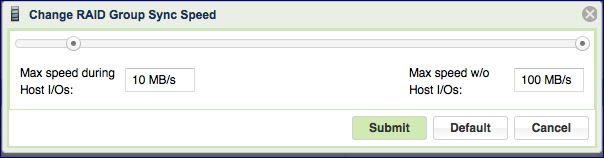
Setting the Sync Speed is a tradeoff between the need to complete the RAID rebuild as quickly as possible in order to return to full redundancy level and the ability to supply good response time and throughput for application IOs. Therefore, the VPSA allows you to control two parameters impacting the sync Speed:
“Max Speed During Host I/Os” – Controls the RAID sync speed when there are Server IOs. You will want to set it low if the Server’s IOs are the priority. Set it high if you want to prioritize the RAID rebuild process.
Default value: 10 MB/s
Range: 1 - 500 MB/s
“Max Speed w/o Host I/Os” – Controls the sync speed when there are no Server IOs. You would typically set it to max value (500 MB/s), unless it consumes too much of the VPSA’s resources (depending on the Engine type) which impacts the performance of other RAID Groups (which do have active Server IOs).
You can set and modify Sync Speed at any time, and it can vary between RAID groups. The Sync Speed also applies to Media Scan (see below).
Understanding Media Scans
Media Scan is the process of checking RAID-6 parity integrity. It reads data and parity from all devices and automatically fixes any inconsistent parity.
This process runs automatically once a month in order to identify and handle any possible silent data integrity issues.
You may want to trigger a Media Scan on a RAID Group manually if, for example, there was an event that is suspected of putting data integrity at risk, such as the failure of two or more drives in a RAID-6 group.
The RAID status will change to “Repairing X%” during the Media Scan. At the end of the Media Scan the results are saved in an event-log message.
You cannot abort a Media Scan that’s in process, but you can pause it by pressing the Pause Media Scan button. The Media Scan button toggles to Pause Media Scan for RAID Groups that are currently being scanned. The RAID status will change to “Repairing Paused” when the Media Scan is paused.
Force Recovery
You can only issue Force Recovery on failed RAID-6 RAID Groups, after one (or more) of the failed drives has been recovered.
If all the drives were recovered, the VPSA will have enough information to determine how to recover the RAID automatically. If two drives are permanently gone in a RAID-6 RAID Group, the VPSA will be unable to determine if the available drives contain the most up-to-date data and hence will be unable to safely decide to automatically recover the RAID Group.
You can instruct the VPSA to perform a “Force Recovery” of the RAID Group which marks all drives as consistent and in-sync and moves the RAID to Normal state.
It is recommended that you run Media Scan following Force Recovery, which will ensure RAID parity consistency (although data may still be inconsistent from the application perspective).
Caution
This operation may result in application data loss. It must be used only when drives are permanently lost and when there are no other alternatives to recover the data.
Replacing a Drive
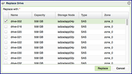
Press the Replace button on the Drives page to replace a drive. When selecting the replacement drive you must choose a drive that will not break the RAID Group redundancy (i.e. you cannot have two or more drives from the same Storage Node in a RAID Group). If you select a drive that has a different type or larger size than the other drives in the RAID Group, you will see a warning, but you can continue the operation.
You can replace a drive in any RAID Group whether the drive is healthy (Normal) or unhealthy (Failed).
You cannot replace a drive if the RAID Group is in a Resyncing state.
Shredding a Drive
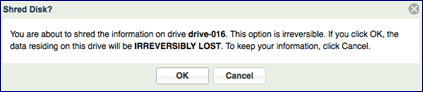
Shredding is the process of erasing the data on a drive for security and privacy reasons by overwriting the entire drive with random data at least three times. Typically you will shred a drive before returning it to the Zadara Cloud or before deleting your VPSA.
You can only perform Shred on drives in Available status (i.e. not in a RAID group).
The Shredding progress appears in the drive status as “Shredding X%” .
You cannot remove a drive from a VPSA while it is being shredded. You need to either cancel the operation by pressing the Cancel Shred button, or wait until shredding is completed.
Caution
Shredding is irreversible!
Viewing Drive properties
You can view the following properties and metering information in the Drives Details South Panel tabs:
Properties
Each drive displays the following Properties:
Property |
Description |
|---|---|
ID |
An internally assigned unique ID. |
Name |
Drive name. |
Capacity |
Drive Capacity in MB. |
Storage Node |
The name of the Storage Node where the drive is physically located. |
Type |
SATA, SAS, or SSD |
Status |
The drive’s status reflects the drive health as sensed by the Storage Node and by the VPSA RAID logic:
|
RAID Group |
Name of the RAID group that contains this drive. |
Protection Zone |
Displays the Protection Zone of the drive. |
Usage |
In-use or Available |
Added |
The date and time when the drive was added to the VPSA. |
Modified |
The date and time when the Drive object was last modified. |
Metering
The Metering Charts provide live metering of the IO workload associated with the selected Drive.
The charts display the metering data as it was captured in the past 20 “Intervals.” An interval length can be set to one of the following: 1 second, 10 Seconds, 1 Minute, 10 Minutes, or 1 Hour. The Auto button lets you see continuously-updating live metering info (refreshed every 3 sec).
The Following charts are displayed:
Chart |
Description |
|---|---|
IOPs |
The number of read and write SCSI commands issued to the Drive, per second. |
Bandwidth (MB\s) |
Total throughput (in MB) of read and write SCSI commands issued to the Drive, per second. |
IO Time (ms) |
Average response time of all read and write SCSI commands issued to the Drive, per selected interval. |
Logs
Displays all event logs associated with this Drive.