Getting Started
This chapter contains step-by-step instructions to create a VPSA and then to configure its storage properties from the Zadara’s Provisioning Portal.
Important
Zadara’s web applications allow only TLS 1.2 and higher, which is the recommended TLS level by industry standards. The TLS (Transport Layer Security) protocol secures transmission of data over the internet using standard encryption technology.
Register a Zadara Account
To register for a new Zadara account, go to https://manage.zadarastorage.com/register/ and complete the registration form. If you wish to provision your new VPSA in a private location please use the URL provided by Zadara for the local Provisioning Portal instance.
Creating a VPSA
Log on to your Zadara Provisioning Portal at https://manage.zadarastorage.com, or at your private cloud, using your username/email and password.
Important
It is recommended to enable MFA (Multi-Factor Authentication) in order to add an additional layer of security to your account.
Click Create New Service.
The Create Zadara Service dialog opens.
Select:
Storage Array to create a hybrid VPSA Storage array.
Flash Array to create a performance-optimized VPSA Flash Array with built-in inline data reduction support.
Click Next to progress to your selection.
Note
VPSA Object Storage creation is described in the VPSA Object Storage User Guide.
Creating a VPSA Storage Array
The Create Storage Array definitions dialog opens after selecting Storage Array in the Provisioning Portal’s Create Zadara Service dialog.
Select Provider and Define Name dialog:
Note
From the public cloud Provisioning Portal you can provision and manage all of your VPSAs, even if they are connected to different cloud provider groups and provider sites.
Enter the following fields:
Provider Group - Select the cloud provider group for your deployment.
Provider - Select the provider site for your deployment.
VPSA Name – Give the VPSA a name. This is how it will appear in the Cloud Console and in the VPSA GUI. If you plan on having multiple VPSAs, you might want to give it as detailed a name as possible.
VPSA Description (Optional) – Give the VPSA a description.
Click Next to continue to the Select Engine Type and Drives configuration.
Select Engine Type and Drives dialog:
Enter the following fields:
Engine Type – The Zadara IO engine type defines the compute characteristics of your VPSA’s Virtual Controllers (VCs). Each engine type defines the following characteristics:
Number of CPUs that are assigned to your VPSA’s VCs.
Amount of RAM that is assigned to your VPSA’s VCs.
Default size of protected SSD Cache.
When selecting the IO engine, take into account the capacity planned for this VPSA. Each engine has a limit to the number of drives it can support, and to the total raw capacity of the VPSA.
You can change the Zadara engine type (upgrade or downgrade) at any time throughout the lifetime of your VPSA according to your application’s needs, on condition that you stay within the maximum limits of the engine type you are moving to.
Note
The compute resources (CPU, RAM and Cache) are dedicated to your VPSA, which ensures consistent performance and isolation from other tenants’ workloads and behavior.
Flash Cache - (for VPSA Storage Array engines larger than 200) - From the dropdown, select the amount of flash cache to allocate to the VPSA. Note that each VPSA engine is provided with a minimum amount of cache memory. The extended cache is allocated in 200GB increments.
Drive Quantities – Select the type and number of drives that you would like allocated to your VPSA.
The Zadara Cloud Orchestrator allocates dedicated drives.
Drives are allocated from as many different SNs as possible to provide maximum redundancy for your VPSA’s RAID groups.
There is a limit to the number of drives per Zadara IO engine type. The larger the engine is, the more drives you can add. There is also a limit to the total raw capacity of all drives. Make sure that the total capacity of all selected drives is within the limit.
The following table lists the maximum drives per VPSA Storage Array engine type:
IO Engine Type
Maximum # of Pools
Maximum # of Drives
Maximum Raw Capacity
200
8
5
24 TB
400
16
10
70 TB
600
32
20
140 TB
800
32
30
180 TB
1000
32
40
240 TB
1200
64
60
300 TB
1600
64
80
400 TB
2400
64
80
800 TB
3600
64
80
1000 TB
Note
While it is technically possible to create a VPSA using the 200 engine to fulfill basic storage needs, it is important to note that such a setup may not be suitable for demanding production workloads. A smaller storage solution typically lacks the necessary scalability and performance capabilities required to handle the rigorous demands of a production environment. In scenarios where data growth, high-volume transactions, or complex data processing are involved, it is strongly advised to start with a larger engine that can ensure optimal performance and reliable storage management. Prioritizing a well-designed storage infrastructure can prevent potential bottlenecks and other issues that may hinder the smooth operation of critical business applications.
Create RAID-10 – By default, at VPSA creation time RAID-10 pools are automatically created, one pool per type of selected drive. The pool includes all the selected drives of each type. If you want to create different pools settings, uncheck this checkbox, and manually create your RAID groups and pools as described in Creating RAID Group, Pools, and Volumes.
Click Next to continue to the Advanced Services configuration.
Advanced Services dialog:
Enter the following fields:
Container Services Engine – The Zadara Container Services (ZCS) Engine defines the compute resources of the VPSA’s Virtual Controllers that are allocated for Docker containers within this VPSA. Refer to Managing Container Services for details about Zadara Container Services.
File Lifecycle Management - Enable file lifecycle management and analytics.
Note
File lifecycle management indexing consumes some VPSA compute and memory resources.
A dedicated indexing repository is created in the VPSA, for file lifecycle management.
Additional SSD volumes are allocated from the VPSA’s existing resources to support file lifecycle management.
Fibre Channel Support – Check this checkbox if you will be connecting hosts to this VPSA over FC SAN.
Click Next to continue to review and confirm your selections.
Review and Confirm dialog:
After selecting the VPSA characteristics, review the displayed summary.
You can click Back to return to previous dialog screens to modify your previous selections.
Press the Create button to confirm the VPSA creation request.
The requested VPSA will appear in the Provisioning Portal’s Service Inventory list, with the Awaiting Approval status.
Completing the VPSA creation requires the approval of a Zadara Storage Cloud admin. Once approved, the new VPSA takes only a few minutes to launch. During that time you’ll see your VPSA with the Launching status and spinner, until launched.
VPSA First Access:
When the VPSA is ready, you’ll receive an email with a temporary passcode at your registered email address.
To access the VPSA GUI, in the Provisioning Portal select the VPSA and under Properties, click the Management Console link.
Note
By default, the VPSA interfaces are accessible to the storage front-end network only.
If you want to access it using a public IP, refer to the Assigning Public IPs section in this guide.
Use your registered username or email address and the temporary passcode to enter the VPSA GUI. You will be immediately prompted to set a new password for your VPSA user account.
Creating a VPSA Flash Array
The Create Flash Array definitions dialog opens after selecting Flash Array in the Provisioning Portal’s Create Zadara Service dialog.
Select Provider and Define Name dialog:
Note
From the public cloud Provisioning Portal you can provision and manage all of your VPSAs, even if they are connected to different cloud provider groups and provider sites.
Enter the following fields:
Provider Group - Select the cloud provider group for your deployment.
Provider - Select the provider site for your deployment.
VPSA Name – Give the VPSA a name. This is how it will appear in the Cloud Console and in the VPSA GUI. If you plan on having multiple VPSAs, you might want to give it as detailed a name as possible.
VPSA Description (Optional) – Give the VPSA a description.
Click Next to continue to the Select Engine Type and Drives configuration.
Select Engine Type and Drives dialog:
Enter the following fields in the VPSA Flash Array’s Select Engine Type and Drives dialog:
Engine Type – The Zadara IO engine type defines the compute characteristics of your VPSA’s Virtual Controllers (VCs). Each engine type defines the following characteristics:
Number of CPUs that are assigned to your VPSA’s VCs.
Amount of RAM that is assigned to your VPSA’s VCs.
When selecting the IO engine, take into account the capacity planned for this VPSA. Each engine has a limit to the number of drives it can support, and to the total raw capacity of the VPSA.
You can change the Zadara engine type (upgrade or downgrade) at any time throughout the lifetime of your VPSA according to your application’s needs, on condition that you stay within the maximum limits of the engine type you are moving to.
Note
The compute resources (CPU, RAM and Cache) are dedicated to your VPSA, which ensures consistent performance and isolation from other tenants’ workloads and behavior.
Drive Quantities – Select the type and number of drives that you would like allocated to your VPSA.
The Zadara Cloud Orchestrator allocates dedicated drives.
Drives are allocated from as many different SNs as possible to provide maximum redundancy for your VPSA’s RAID groups.
There is a limit to the number of drives per Zadara IO engine type. The larger the engine is, the more drives you can add. There is also a limit to the total raw capacity of all drives. Make sure that the total capacity of all selected drives is within the limit.
The following table lists the maximum drives and capacity per VPSA Flash Array Engine type:
Note
Due to VPSA Flash Array data reduction, the capacity limit per engine depends on both the physical capacity of the drives and the customer virtual capacity (as seen by the hosts), before any data reduction.
More about VPSA Flash Array capacities: Understanding Pool’s Capacity (VPSA Flash Array)
IO Engine Type
Maximum # of Pools
Maximum # of Drives
Maximum Raw Capacity
Maximum Provisioned Capacity
H100
1
60
280 TB
140 TB
H200
2
80
440 TB
220 TB
H300
2
120
800 TB
400 TB
H400
2
140
1000 TB
500 TB
The high tier (also known as tier 0) is the more performant tier of the VPSA, and comprises in-array SSD/NVME drives.
The low tier (also known as tier 1) is the capacity-oriented tier of the VPSA.
It can be implemented via in-array SATA/NLSAS drives, or by connectivity to a remote object storage container.
SSD Storage Class: The number of SSD type drives for Tier 0 (high tier).
HDD Storage Class: The number of HDD type drives for Tier 1 (low tier).
For more information on tiers see Tiers in Understanding Storage Pools.
Note
The above capacities depend on the type of the pool(s) used.
The numbers shown are the limits of the aggregated size of all pools of type Throughput-Optimized.
See Creating a Pool for details
Create RAID-10 – By default, at VPSA creation time RAID-10 pools are automatically created, one pool per type of selected drive. The pool includes all the selected drives of each type. If you want to create different pools settings, uncheck this checkbox, and manually create your RAID groups and pools as described in Creating RAID Group, Pools, and Volumes.
Click Next to continue to the Advanced Services configuration.
Advanced Services dialog:
Enter the following fields:
Container Services Engine – The Zadara Container Services (ZCS) Engine defines the compute resources of the VPSA’s Virtual Controllers that are allocated for Docker containers within this VPSA. Refer to Managing Container Services for details about Zadara Container Services.
File Lifecycle Management - Enable file lifecycle management and analytics.
Note
File lifecycle management indexing consumes some VPSA compute and memory resources.
A dedicated indexing repository is created in the VPSA, for file lifecycle management.
Additional SSD volumes are allocated from the VPSA’s existing resources to support file lifecycle management.
Usage of the File Lifecycle Management service incurs additional charges.
Data Reduction Bundle - Enable support for:
Inline data compression
Inline data deduplication
Note
Usage of the Data Reduction service incurs additional charges.
Click Next to continue to review and confirm your selections.
Review and Confirm dialog:
After selecting the VPSA characteristics, review the displayed summary.
You can click Back to return to previous dialog screens to modify your previous selections.
Press the Create button to confirm the VPSA creation request.
The requested VPSA will appear in the Provisioning Portal’s Service Inventory list, with the Awaiting Approval status.
Completing the VPSA creation requires the approval of a Zadara Storage Cloud admin. Once approved, the new VPSA takes only a few minutes to launch. During that time you’ll see your VPSA with the Launching status and spinner, until launched.
VPSA First Access:
When the VPSA is ready, you’ll receive an email with a temporary passcode at your registered email address.
To access the VPSA GUI, in the Provisioning Portal select the VPSA and under Properties, click the Management Console link.
Note
By default, the VPSA interfaces are accessible to the storage front-end network only.
If you want to access it using a public IP, refer to the Assigning Public IPs section in this guide.
Use your registered username or email address and the temporary passcode to enter the VPSA GUI. You will be immediately prompted to set a new password for your VPSA user account.
Creating RAID Group, Pools, and Volumes
By default a new VPSA is created with all its drives configured in RAID Groups, and a Pool per each drives type. If the automatic pools satisfy your needs, go directly to the volumes creation below.
Otherwise follow the RAID Group and Pool creation instruction:
Create a RAID Group to define the level of data protection needed.
For more details, see Creating a RAID Group.
Create a storage pool by using aggregated capacity from one or more RAID Groups.
For more details, see Creating a Pool.
Create an iSCSI / FC / NFS / SMB Thin Provisioned Volume to be used by your servers.
For more details, see Creating and Deleting a Volume.
Add a server. The server object represents the host using the storage volume.
Follow the instructions depending on the OS and connectivity of your server: Adding a Server
Attach the Volume to a Server.
For more details, see Attaching & detaching Volumes to Servers
Congratulations! You have a new VPSA provisioned and ready to use.
The following sections describe the various capabilities and services of your VPSA in detail.
Managing your VPSA’s resources
You create, add, change, delete and manage the resources comprising your VPSAs via the Zadara Provisioning Portal.
This section describes the operations available in the Provisioning Portal (https://manage.zadarastorage.com).
Adding and removing Disk Drives
To add drives to your VPSA go to the Provisioning Portal, select the VPSA, and from the Actions dropdown select Add Drives.
Select the number of drives from each available drive type you wish to add to your VPSA, and press Add. Keep in mind the RAID Groups you are going to build.
This operation requires the approval of a Zadara Storage Cloud Admin. Once approved, you’ll see the number of drives in the Provisioning Portal update accordingly. If you then refresh the Drives page in the VPSA GUI, the new drives will be displayed.
You can remove unused drives (indicated by the Available status) from within the VPSA.
In the VPSA GUI, go to the Drives page, select the drive you wish to remove and press Remove.
If you wish to remove a drive that is part of a RAID Group, you first need to replace it with another drive as described in Replacing a Drive.
Managing Zadara Engines
The Zadara IO Engine type defines the following characteristics of your VPSA’s Storage Controllers:
Dedicated CPU and memory resources - These are dedicated solely to your VPSA. These resources are not shared with any other VPSA or tenant within the Zadara Storage Cloud.
Flash Cache Size (VPSA Storage Array only) - Each VPSA is provisioned with a Flash Cache partition to be used for both metadata and read/write caching. The SSD cache partition is protected using RAID-1, where each mirror copy resides on a different SN, thus ensuring cache resilience to SN failure. Each Engine type is provided with a base SSD cache partition size. You can request additional flash capacity for caching. For more details see “Adjusting Cache.”
Maximum number of drives – The maximum number of drives that can be allocated to each VPSA engine type.
The following Zadara IO Engines are available for VPSA Storage Arrays:
IO Engine Type |
Dedicated Compute Resources |
Base Flash Cache |
Max # of Drives |
Max Raw Capacity |
|---|---|---|---|---|
200 |
2 CPU, 6 GB RAM |
20 GB |
5 |
24 TB |
400 |
4 CPU, 12 GB RAM |
20 GB |
10 |
70 TB |
600 |
6 CPU, 20 GB RAM |
40 GB |
20 |
140 TB |
800 |
8 CPU, 28 GB RAM |
60 GB |
30 |
180 TB |
1000 |
10 CPU, 36 GB RAM |
80 GB |
40 |
240 TB |
1200 |
12 CPU, 52 GB RAM |
100 GB |
60 |
300 TB |
1600 |
16 CPU, 68 GB RAM |
120 GB |
80 |
400 TB |
2400 |
24 CPU, 100 GB RAM |
180 GB |
80 |
800 TB |
3600 |
36 CPU, 144 GB RAM |
240 GB |
80 |
1000 TB |
The following Zadara IO Engines are available for VPSA Flash Arrays:
IO Engine Type |
Dedicated Compute Resources |
Maximum # of Drives |
Maximum Raw Capacity |
Maximum Provisioned Capacity |
|---|---|---|---|---|
H100 |
12 CPU, 72 GB RAM |
60 |
280 |
140 TB |
H200 |
24 CPU, 116 GB RAM |
80 |
440 |
220 TB |
H300 |
36 CPU, 176 GB RAM |
120 |
800 |
400 TB |
H400 |
48 CPU, 236 GB RAM |
140 |
1000 |
500 TB |
Note
Due to data reduction in a VPSA Flash Array, the capacity limit per engine depends on both the physical capacity of the drives and the provisioned capacity, before any data reduction.
The above capacities depend on the type of the pool used. The numbers shown are the limits of the aggregated size of all pools of type Throughput-Optimized. See Creating a Pool for details.
More about VPSA Flash Array capacities: Understanding Pool’s Capacity (VPSA Flash Array)
The following Zadara Container Services Engines (see: Managing Container Services) are available:
Zadara ZCS Engine Type |
Dedicated compute resources |
|---|---|
01 |
2 CPU, 512 MB RAM |
02 |
2 CPU, 1 GB RAM |
04 |
4 CPU, 2 GB RAM |
06 |
6 CPU, 4 GB RAM |
08 |
8 CPU, 8 GB RAM |
To change both types of Zadara Engines, in the Provisioning Portal select the VPSA, and from the Actions dropdown select Change Engine Type.
When selecting any engine larger than 200 you can also select the required flash cache size for that engine. For Flash Cache limits see here.
Completing this operation requires the approval of the Zadara Storage Cloud Admin.
The Zadara Engine upgrade/downgrade process may take a few minutes. During that time, the VPSA status will change to Upgrade Pending.
When the process completes, the VPSA status will change back to Ready.
Managing Virtual Networks
The Zadara cloud provides a flexible and dynamic virtual networking infrastructure that can be tailored to meet multiple storage architecture and use cases.
Each cloud tennant is allocated with one or more “Virutal Networks” which is a set of available IP addresses within a specific network segment. Virtual networks are allocated for a specific cloud tenneant and within a specific avilable cloud VLAN.
The below diagram depicts the relationship between cloud tenants, virtual networks and VLANs:
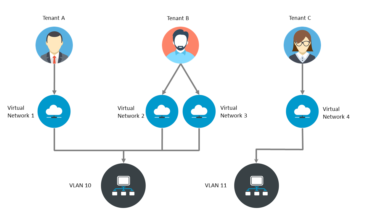
In case a VPSA serves as storage for servers on different networks, the VPSA can be plugged on multiple “Virtual Networks”. Both block volumes and NAS shares can simultaneously be exposed through one or more Virtual Networks.
Each VPSA is created with a primary network for its front end (hosts connectivity). This network is routable and is mandatory.
You can manage your virtual networks from the Zadara Provisioning Portal. In the Provisioning Portal, click your account at the top right, and in the dropdown, click Network Management.
To create another virtual network press Next, and fill in the requested parameters such as: CIDR, Gateway, IP Range, and whether IPv4 or IPv6 should be used.
You can add and remove secondary networks to the VPSA. The VPSA internally maintains a “Virtual Networks Interface” (VNI) that connects into each virtual networks.
To add a Virtual Network Interface, in the Provisioning Portal select the VPSA, and from the Actions dropdown select Add Virtual Network Interface.
To remove a Virtual Network Interface, in the Provisioning Portal select the VPSA, and from the Actions dropdown select Remove Virtual Network Interface.
Note
Number of VNIs per VPSA is limited to 5.
VPSA REST API/GUI is accessible through any VNI.
Only Primary VN IP is registered in DNSimple
VPSA can’t have two VNI with the same VLAN.
Note
Only “Primary Virtual Network” is a routable network. Remaining virtual networks are not routable. There are some limitations on the remaining virtual networks:
Active Directory can be joined only through “primary virtual network”.
Backup (B2OS), Mirror, Remote Clone through FE network are only allowed via the “primary virtual network”.
ZCS container services exposed through FE network can be done only on “primary virtual network”.
“iSER” host connectivity is available only on the “Primary Virtual Network”.
Assigning Public IPs
By default you cannot access the VPSA from the public Internet for security and privacy reasons. The VPSA Front-End IP address which is used for VPSA management (via GUI and REST API) and for data IO workload (host connectivity via iSCSI/NFS/SMB protocols), is allocated on the Zadara Storage Cloud “Front-End” network 10GbE interface which is routable only from the Cloud Servers network. Servers outside of your Cloud Servers network cannot reach this IP address. This means you cannot access your VPSA GUI from the Internet.
A typical use case requiring Public IP addresses is when you’re running Asynchronous Remote Mirroring between two VPSAs in different regions, between on premise and cloud deployments or even between different Cloud Providers for Disaster Recovery (DR). Communication between the VPSAs is done via an authenticated and encrypted channel over the public Internet, thus requiring Public IPs.
To assign a Public IP address to your VPSA, go to the Provisioning Portal and press the Assign Public IP link. You can see the assigned IP address in your VPSA details in the Provisioning Portal and in the VPSA GUI, under Settings > General > Public IP. To remove it, click Remove Public IP in the Provisioning Portal.
Note
Access to the VPSA GUI and API is blocked through the Public IP for security reasons.
Note
NAT’d server IP connections are not supported for iSCSI, NFS, and SMB protocols over the Public IP.
Adjusting Flash Cache (VPSA Storage Array)
Each VPSA is provisioned with a base flash cache partition, which is utilized by the VPSA for both metadata and read/write caching. The initially assigned default SSD cache size is also the minimal cache size for a given Zadara Engine. The flash cache partition is protected using RAID-1, where each mirror copy resides on a different SN, thus ensuring cache resilience to multiple types of failure.
On top of the base flash cache described above, you can add an extended cache. The VPSA extended flash cache size is elastic, so you can increase or decrease the cache size according to the needs of your workload.
Each Engine type has a minimum (default) and maximum SSD Cache size, as shown in the table below:
Zadara Engine |
Base Flash Cache |
Default Extended Flash Cache Size |
Max Extended Flash Cache Size |
|---|---|---|---|
200 |
20 GB |
0 GB |
0 GB |
400 |
20 GB |
200 GB |
400 GB |
600 |
40 GB |
400 GB |
800 GB |
800 |
60 GB |
600 GB |
1200 GB |
1000 |
80 GB |
800 GB |
1600 GB |
1200 |
100 GB |
1200 GB |
2400 GB |
1600 |
120 GB |
1600 GB |
3200 GB |
2400 |
180 GB |
1600 GB |
3200 GB |
3600 |
240 GB |
1600 GB |
3200 GB |
To change the Extended Flash Cache size for your VPSA, in the Provisioning Portal select the VPSA, and from the Actions dropdown select Change Flash Cache.
Upgrading your VPSA
From zStorage 23.09, the self-service VPSA software update process is available in Zadara’s Provisioning Portal. The self-service option streamlines and accelerates the VPSA update process. VPSA owners can now determine VPSA update schedules at their own convenience. The self-service software update can be run immediately, or scheduled to run in 30 minutes from the current time, up to 7 days from the current date and time.
Important
Per Zadara’s Software Lifecycle Policy, only VPSAs that are running software versions that have not entered the End of Support phase are eligible for self-service software updates.
The update takes up to 20 minutes on the standby controller, followed by the VPSA initiating a single failover, during which IOs are paused for several seconds and resume automatically.
In the Service Inventory list of the Provisioning Portal’s
Console, the Update Available! badge displays next to the VPSA’s
Service Type.
To update a VPSA:
In the Provisioning Portal, in the Console’s Service Inventory list, either click the eligible VPSA’s
Update Available!badge, or click the VPSA row to open the VPSA’s details pane on the right, and in the Actions dropdown menu, select VPSA Software Update.The update process runs checks to verify that the VPSA’s state allows an upgrade. For example, if the VPSA’s state is
Degradedor the VPSA is running an older software version that cannot be upgraded directly, a relevant message is displayed directing users to contact Zadara Support.On successful verification of the VPSA for the self-service update, the VPSA Software Update dialog opens. The VPSA’s current running version is displayed, as well as the new zStorage software version that is available for update, together with the link to its release notes. This is followed by a brief description of the flow of the marked update process (Now or Schedule an update for later).
Select the update schedule:
Now
Important
On confirmation, the VPSA software update process is executed immediately, and takes up to 20 minutes to complete.
The standby controller is updated with the latest software version. This is followed by the VPSA initiating a single failover to complete the software update, during which IOs are paused for several seconds and resume automatically.
Enter your Provisioning Portal login password, and click UPDATE.
The
Update software version startedmessage is displayed.Click OK to close the dialog.
Note
On the next refresh of the Console’s Service Inventory list, the VPSA’s Status display changes to
Upgrading Version.On completion of the update process, the VPSA’s Status display changes briefly to
Reconfiguring, and then back toCreated.Schedule an update for later
Enter a date and time, in the range of 30 minutes from the current time, up to 7 days from the current date and time.
The default is one hour from the current time.
Enter your Provisioning Portal login password, and click UPDATE.
Important
When scheduling an update for your VPSA software at a later time:
The VPSA’s standby controller is updated immediately with the new software version, in preparation for the scheduled failover to the new version. The update takes about 20 minutes.
Prior to a scheduled update, the system sends email reminders to the VPSA owner:
A notification 8 hours before the scheduled update time.
A final notification 10 minutes before the scheduled update time.
At the scheduled time, the VPSA initiates a single failover to complete the software update during which IOs are paused for several seconds, and resume automatically.
To reschedule a scheduled VPSA upgrade:
Click the eligible VPSA’s
Update Available!badge, or click the VPSA row to open the VPSA’s details pane on the right, and in the Actions dropdown menu, select VPSA Software Update.In the Reschedule VPSA Software Update dialog that opens, select one of:
Now
The previously scheduled update had already updated the standby controller with the new software version, in preparation for its scheduled failover.
Select Now to trigger an immediate failover to the standby controller to complete the update, during which IOs are paused for several seconds, and resume automatically.
Schedule an update for later
The previously scheduled update had already updated the standby controller with the new software version, in preparation for its scheduled failover.
Enter a new date and time to reschedule the failover to the updated standby controller, in the range of 30 minutes from the current time, up to 7 days from the current date and time.
Enter your Provisioning Portal login password.
Click Reschedule to apply the new schedule, or Cancel to remain with the original schedule.
The self-service update process:
Logs the self-service VPSA software update request in the Provisioning Portal’s access logs.
Sends an automatic email notification to VPSA owners on completion of the VPSA software update, advising them of the successful VPSA software update.
Hibernating your VPSA
You can hibernate your VPSA when it is not in use for some period of time in order to reduce its associated service cost. While the VPSA is in a hibernated state you will only be billed for the drives, not the engine. Hibernating a VPSA involves the process of deleting its Virtual Controllers (the VPSA) while maintaining the data drives and all the necessary metadata to resume its operation at a later stage. No data is lost! The hibernated VPSA is not accessible to any GUI or REST API commands, nor will it present any iSCSI or NFS / SMB volumes. Resuming a hibernated VPSA only takes a few minutes.
To change the Extended Flash Cache size for your VPSA, in the Provisioning Portal select the VPSA, and from the Actions dropdown select Hibernate.
To resume access to the VPSA, in the Provisioning Portal select the VPSA, and from the Actions dropdown select Restore.
Note
The Hibernate and Restore toggle depends on the current state of the VPSA
Deleting your VPSA
Warning
Please note that deleting a VPSA is a significant action and should be done with caution. Ensure that you have backed up any critical data and that you are certain you want to proceed with the deletion
The VPSA owner can delete their VPSA using Zadara’s Provisioning Portal in case it is no longer needed. The delete operation will delete all VPSA entities such as volumes,pools,raid-groups,drives and server records.
In order to delete a VPSA select the Delete action from the Actions dropdown menu in Zadara’s Provisioning Portal. The delete operation will require an additional authentication confirmation.
Due to the sensitive nature of the delete operation, when the VPSA owner initiates a delete operation, it will generate a delete request that necessitates approval from a cloud administrator. Once approved, the VPSA will be permanently deleted.
Note
While the delete request is still pending, the VPSA will continue to operate normally and will continue to report its consumption to the cloud’s billing services
The VPSA Interface
Note
The VPSA management interface web application is supported in all modern browsers. We recommend using Google Chrome, Firefox or Microsoft Edge for an optimal user experience.
Understanding the VPSA Dashboard
VPSA Dashboard is the landing page, every time the GUI opens. It gives the overall state of the VPSA (Health, Capacity, Performance) at a glance. The Dashboard has the following components:
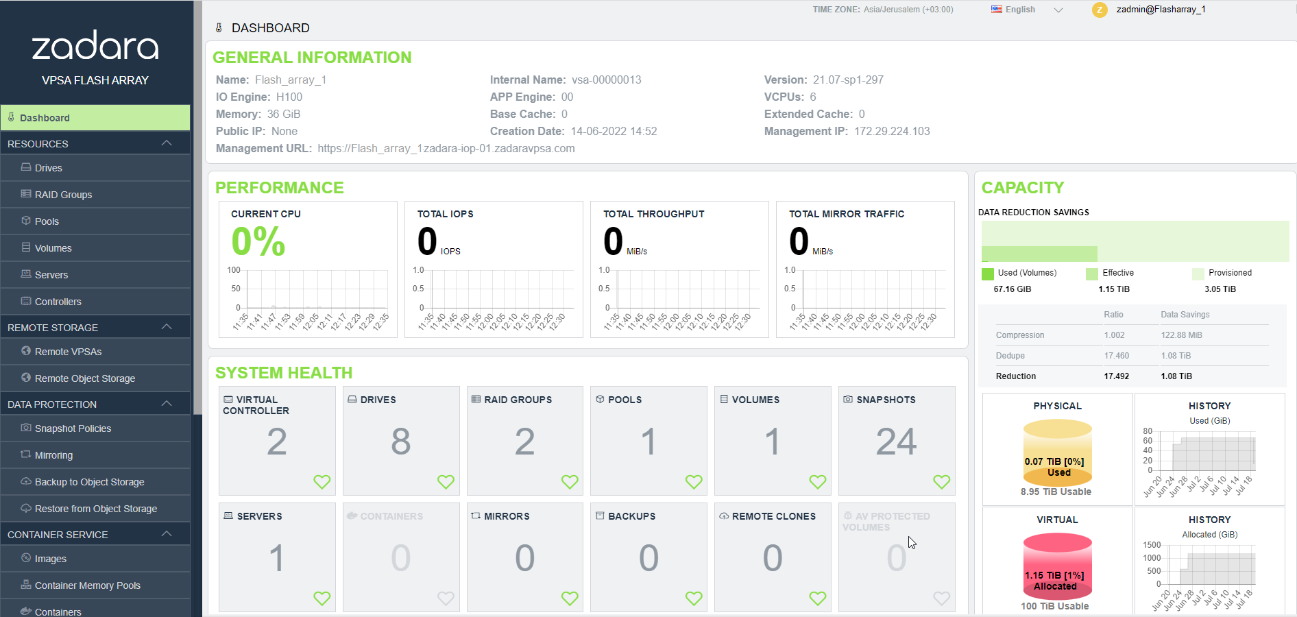
VPSA Info: General information of the VPSA such as its name, engine type and management IP address.
System Health: Shows the inventory of the objects managed by the system, such as Pools, Volumes, Mirrors, and so on. If all objects of a component are in the normal state, there is a green indicator on the component’s tile. If there is situation that needs your attention a red indicator is shown on the component’s tile, with the number of objects requiring attention.
CPU: Shows the CPU utilization of the active Controller of the VPSA, over time. This chart gives an indication of the load on the storage system.
Capacity: Shows the capacity state of the VPSA. The display is different between VPSA Storage Array and VPSA Flash Array. For the latter, it shows the capacity reduction saving. See Understanding Pool’s Capacity (VPSA Flash Array) for details.
Current capacity state
Capacity consumption over time during the last month
Performance: These charts show the aggregated performance of all Volumes.
Current IOPS (reads and writes) of all Volumes
IOPS activity during the last hour
Current throughput of all Volumes
Throughput of all volumes during the last hour
Current mirroring traffic of all mirrors (outbound and inbound)
Mirroring activity of all mirrors during the last hour
Understanding the VPSA GUI
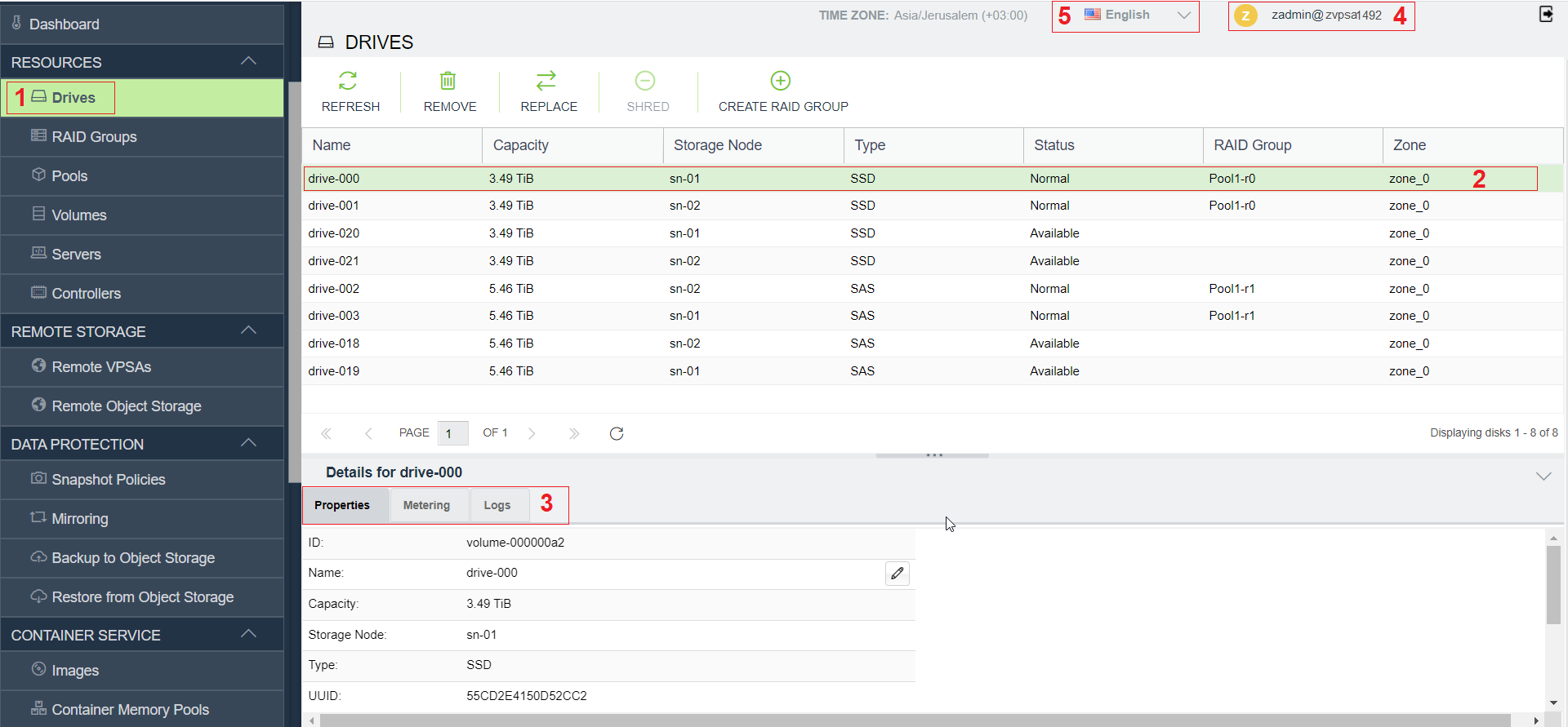
The VPSA GUI provides full management and control of your VPSA. It contains the following main components (as numbered in the above screenshot):
Main Navigation Left Panel – Traverse through the various VPSA entities. The selected entity is highlighted.
The Center Pane – Displays a list of objects from the selected entity type (e.g. Drives in the above screenshot example) and for each object it displays the main properties.
The South Pane – Displays detailed information regarding the selected object. All objects have at least 3 tabs:
Properties – Detailed properties of the object.
Metering – Typically IO workload metering info.
Logs – List of event-log messages related to that object.
Logged-in username – Displayed at the top right corner.
Selected Language – Displayed on the top bar. You can use this drop down to change the displayed language.
System notifications
VPSA notifications, both informational and critical, necessitating user action, will be communicated via email to the service owner and other designated users set to receive notifications.
System notifications are categorized based on the following priorities:
Urgent
High
Normal
Low
Urgent priority notification
An alert that requires an immediate VPSA administrator action to ensure the storage service health or to restore the VPSA to normal operation, for example:
Pool free capacity state
System is pending for Master Encryption key from the administrator
High priority notification
An alert that requires awareness of the VPSA administrator to ensure the storage service health or other service issues that are currently being handled by Zadara’s support team. In some cases VPSA administrator action is required.
Example for high priority notifications:
Volume out of free space
Duplicate Front-End IP discovery
Normal priority notification
An alert that requires the administrator’s attention, yet does not necessarily have an immediate impact on the service. For example:
Temporary Active Directory domain controller connectivity issue
VPSA connectivity issue to a server that was set with connectivity test option
Low priority notification
A low-priority message with no impact on service health. While the message may require attention or action from administrators, its lower priority status indicates that it poses minimal or no threat to the current state of the service and can be addressed at the convenience of the administrators without causing service disruptions.
For example:
Volume low capacity
Volume auto-expand confirmation