VPSA (Virtual Private Storage Arrays)
Using Command Center, cloud administrators can manage and monitor Virtual Private Storage Array instances running in the cloud. Command Center’s VPSA management feature set provides administrators with a single pane of glass, in which administrators receive a holistic image of the underlying instance’s status and operations, and allows for enforcements of policies, lifecycle management and supervised resource distribution.
Important
Administrators are recommended not to change any configurations, unless directed to do so by Zadara Support.
Viewing Virtual Private Storage Array Properties
To view a specific VPSA:
Click VPSAs in Command Center’s left menu panel.
In the VPSAs grid, click the VPSA instance.
VPSA Instance Dashboard
The VPSA instance’s main Dashboard tab’s Information panel provides information regarding the VPSA’s configuration, current health status and network topology.
Property |
Description |
|---|---|
Name |
VPSA instance’s display name |
Internal Name |
VPSA instance’s internal name |
User |
User who created the instance |
Company |
Company of the user who created the instance |
Description |
Description given when the instance was provisioned |
Nova ID |
VPSA instance’s Nova ID |
Status |
Current status of the instance |
Protection Zone |
Instance Protection Zone configuration |
Image |
Instance deployment image |
IO Engine Type |
VPSA IO Engine Flavor |
App Engine Type |
VPSA APP Engine Flavor |
VCPUs |
Instance VCPU count |
RAM |
Instance configured RAM capacity |
Base Cache |
Instance Base Cache capacity |
Extended Cache |
Instance Extended SSD cache configured capacity |
Setup Volume Capacity |
Instance setup volume capacity |
IP Address |
Instance floating frontend IP address |
Public IP |
Instance public IP address |
Mgmt. Address |
Instance hostname for management access |
UUID |
Instance UUID |
SNMPv3 Engine ID |
Instance SNMPv3 Engine ID |
Created |
Instance creation timestamp |
Updated |
Instance last update timestamp |
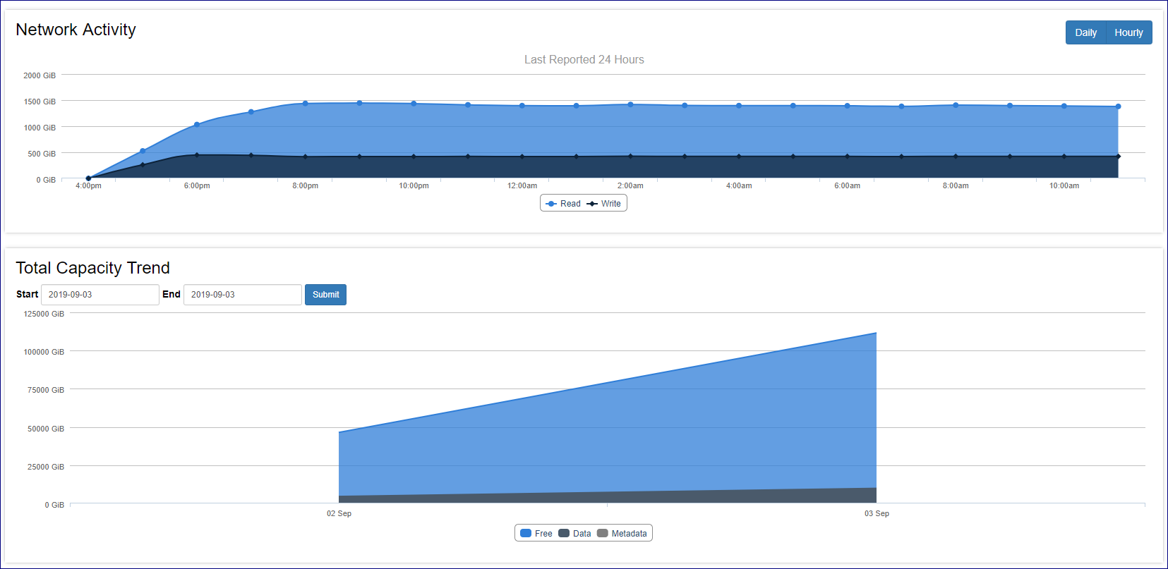
The VPSA instance’s main Dashboard tab provides monitoring charts with adjustable time period views:
Network Activity chart
Total Capacity Trend chart displaying capacity utilization
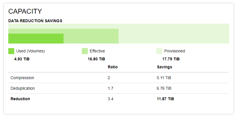
VPSA Flash Array: The main Dashboard tab also displays the Capacity Data Reduction Savings panel:
A chart comparing used capacity, provisioned and effective capacity.
Information about savings from inline data deduplication and inline data compression, and the VPSA overall data reduction ratio.
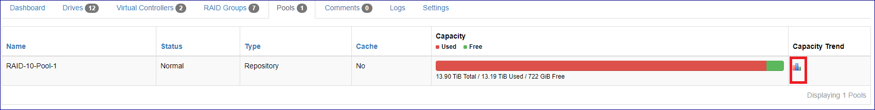
The VPSA resource tabs provide information regarding underlying resources attached to the VPSA:
Physical Drives
Virtual Controllers
RAID Groups
Pools
Note
The RAID Group tab also displays information on internal groups such as Metering and Journal, which are not visible or accessible to VPSA users.
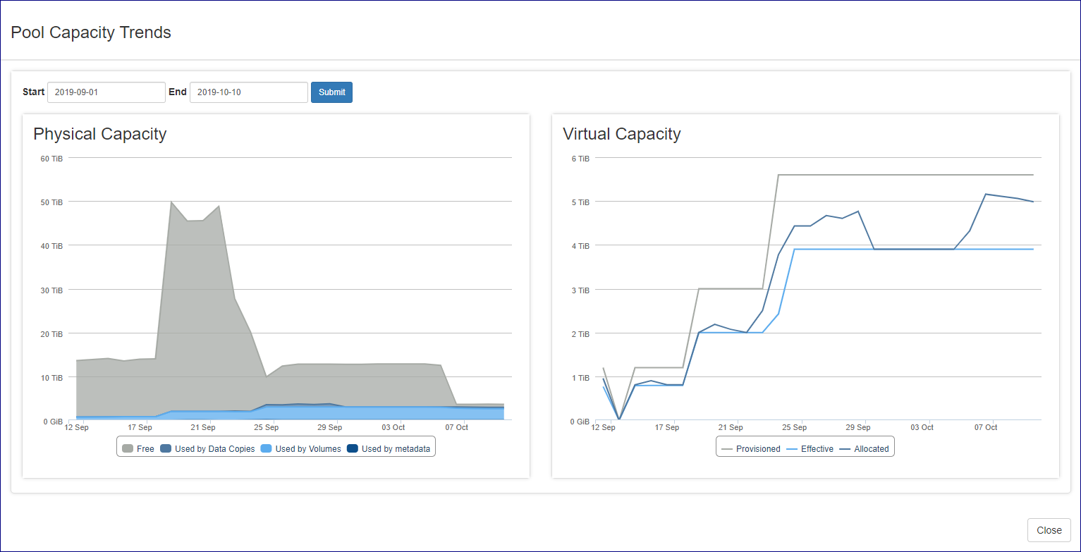
VPSA Pools tab
The VPSA Pools tab displays consumption in Pool Capacity Trend charts. These charts provide cloud administration with an overview of the Pool’s capacity change over time, and the effect of data reduction mechanisms such as deduplication and compression on VPSA Flash Array Pools.
To view the capacity trend for a specific Pool:
Navigate to the VPSA’s Pools tab.
In the Pools grid, click the charts icon in the Pool’s Capacity Trend column.
Pool Capacity Trends charts display capcity trends over a period of time, defaulting to the past month.
To change the trend display period, enter the Start and End dates, and click Submit.
Pool Capacity Trends chart styles
The Pool Capacity Trends chart styles depend on the type of VPSA:
VPSA Storage Array:
A single chart displays the overall Free, Data and Metadata Pool Capacity Trends over time.
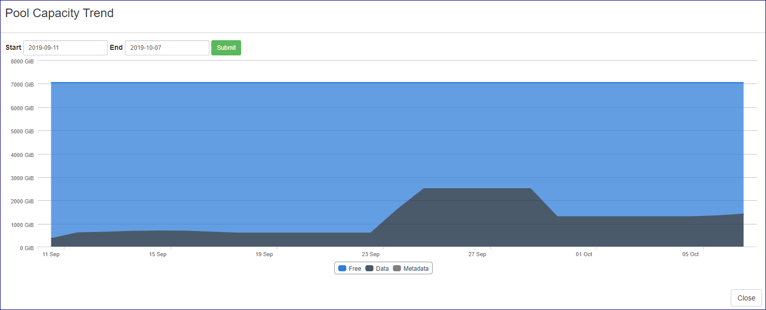
VPSA Flash Array: Two charts display the Pool’s Capacity Trends:
Physical Capacity: Overall Pool Capacity trends over time:
Free
Used by Data Copies
Used by volumes
Used by metadata
Virtual Capacity: Comparison of Provisioned Capacity, Virtual Capacity and Effective Capacity trends over time.
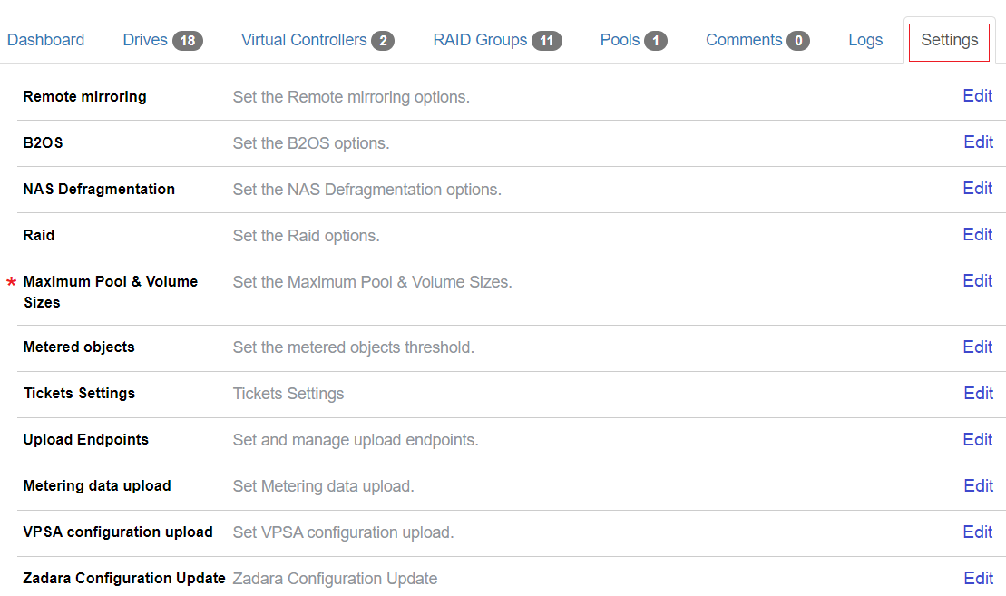
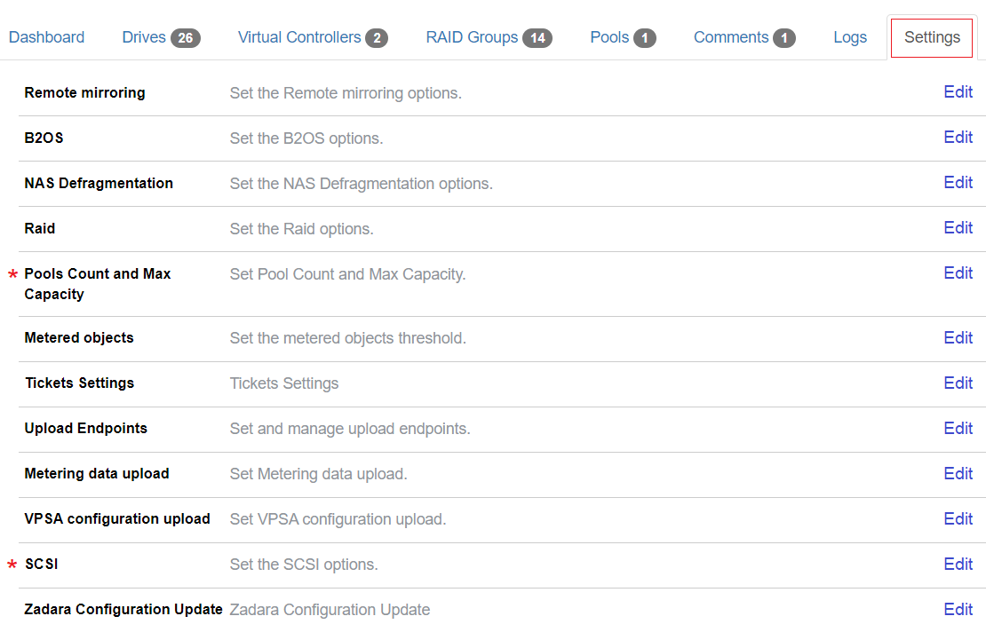
Configuring Virtual Private Storage Array Settings
Note
Most of the VPSA settings for VPSA Storage Array and VPSA Flash Array are identical.
Differences are highlighted.
To view or alter VPSA settings:
Click the VPSA’s Settings tab.
Click Edit on a specific setting to view or update its details.
VPSA Storage Array Settings:
VPSA Flash Array Settings:
Remote mirroring properties
Parameter |
Description |
|---|---|
Dst total quota pc |
Allowance for amount of unapplied data for all VPSA mirror jobs 0 - No quota enforcement |
Connections count |
Number of TCP sessions established between two VPSAs performing mirroring |
Backup to Object Storage (B2OS)
Parameter |
Description |
|---|---|
Src buffers count |
Amount of source buffers allocated for B2OS activities |
Dst buffers count |
Amount of destination buffers allocated for B2OS activities |
NAS Defragmentation
Parameter |
Description |
|---|---|
Minimum extents count |
Number of extents a file needs to have to be considered for defragmentation |
Minimum file alignment percent VPSA Flash Array |
Defrag files of size greater than “Minimum file size in KiB” AND have less than “Minimum file alignment percent” of extents that are not aligned to pool LSA chunk size. |
Minimum file size in kib VPSA Flash Array |
Defrag files of size greater than “Minimum file size in KiB” AND have less than “Minimum file alignment percent” of extents that are not aligned to pool LSA chunk size. |
Note
Scope: VPSA Flash Array
For a file defragmention to occur, both of the following conditions must apply:
The file’s size is greater than the Minimum file size in KiB
The file has fewer extents than the Minimum file alignment percent that are not aligned to the Pool’s LSA chunk size
RAID
Parameter |
Description |
|---|---|
Allow mixed types |
Enable allowing a mix of HDD types in the sameRAID Group or Pool |
Maximum Pool & Volume Sizes
Scope: VPSA Storage Array
Parameter |
Description |
|---|---|
Pool transactional max size |
Maximum capacity (TiB) of a transactional pool |
Pool repository max size |
Maximum capacity (TiB) of a repository pool |
Pool archival max size |
Maximum capacity (TiB) of an archival pool |
Pool depot max size |
Maximum capacity (TiB) of a depot pool |
Pools Count and Max Capacity
Scope VPSA Flash Array
Parameter |
Description |
|---|---|
Pool iops optimized allocation limit capacity in tib |
Pool IOPs optimized allocation limit capacity in TiB |
Pool balanced allocation limit capacity in tib |
Pool balanced max mapped capacity in TiB |
Pool throughput optimized allocation limit capacity in tib |
Pool throughput optimized max mapped capacity in TiB |
Maximum number of pools |
Max Number of Pools allowed for this VPSA |
Metered objects
Parameter |
Description |
|---|---|
Check interval |
Interval in seconds for validation of metered objects threshold alerts |
Report interval |
Interval in seconds for rate limiting all metered objects thresholds alerts |
Read cache late IO threshold |
Amount of read hit IO operations with late time exception required to trigger an alert |
Read cache late IO threshold time(ms) |
Read hit IO operation service time value that is considered as late IO |
Write cache late IO threshold |
Amount of write hit IO operations with late time exception required to trigger an alert |
Write cache late IO threshold time (ms) |
Write hit IO operation service time value that is considered as late IO |
Enable metering upload agent |
Enable upload of metering data to an external cloud repository |
Ticket Settings
See Managing Cloud Settings > Management Settings in this manual for details regarding the ticket settings section.
Upload Endpoints
The cloud administrator can configure alternative endpoints for uploading cloud Zsnaps, MAG and configuration information.
Expanding the Upload Enpoints section displays details of the cloud’s configured endpoints.
Upload endpoints can be of the following types:
AWS S3 endpoint
Parameter
Description
Endpoint name
The endpoint’s name
Method
AWS S3
Access Key
Endpoint access key
Secret Key
Endpoint secret key
Region
AWS region
Object Storage endpoint
Parameter
Description
Endpoint name
The endpoint’s name
Method
ZIOS S3
Access Key
Endpoint access key
Secret Key
Endpoint secret key
Endpoint
Object Storage FQDN
FTP target
Parameter
Description
Endpoint name
The endpoint’s name
Method
FTP
Server
FTP server
User
Username
Password
Password
Use Proxy
Whether to use a proxy for the connection
Creating a new endpoint
To create a new endpoint:
Expand the Upload Endpoints section.
At the top right of this section, click New.
In the Create Upload Endpoint dialog, select the endpoint Method from the dropdown list, and enter the other parameters relevant to its Method.
Click Save.
Editing an endpoint
To edit an endpoint:
Expand the Upload Endpoints section.
Locate the endpoint to edit. In its Actions column, click Edit.
Note
Some system-supplied endpoints are not editable.
In the Edit Upload Endpoint dialog, update the relevant parameters.
Note
The endpoint’s Name and Method can not be changed.
Click Save.
Deleting an endpoint
To delete an endpoint:
Expand the Upload Endpoints section.
Locate the endpoint to delete. In its Actions column, click Delete.
Note
Some system-supplied endpoints can not be deleted.
In the Delete Upload Endpoint dialog, confirm the deletion.
Metering data upload
The cloud administrator can configure the target endpoints to which metering data can be uploaded. Up to three AWS S3 endpoints can be configured for metering data uploads.
Adding an additional endpoint
To add an additional upload endpoint:
Expand the Metering data upload section.
Click Add Another.
Select the Endpoint from the dropdown and enter the Bucket.
Parameter
Description
Endpoint
Endpoint for metering data upload
Bucket
Bucket for metering data upload
Click Update.
Removing an additional endpoint
To remove an additional endpoint:
Expand the Metering data upload section.
Locate the additional endpoint to remove and click Discard Endpoint.
Click Update.
VPSA configuration upload
The cloud administrator can configure the target endpoints to which metadata from this cloud for Zadara management and analysis can be uploaded. Up to three AWS S3 endpoints can be configured for these uploads.
Adding an additional endpoint
To add an additional upload endpoint:
Expand the VPSA configuration upload section.
Click Add Another.
Select the Endpoint from the dropdown and enter the Bucket.
Parameter
Description
Endpoint
Endpoint for metering data upload
Bucket
Bucket for metering data upload
Click Update.
Removing an additional endpoint
To remove an additional endpoint:
Expand the VPSA configuration upload section.
Locate the additional endpoint to remove and click Discard Endpoint.
Click Update.
SCSI
Scope: VPSA Flash Array
VPSA Block Volume XCopy Concurrency
Zadara Configuration Update
Administrators can define Zadara Configuration Keys.
Creating Zadara Configuration Keys
To create a new Configuration Key:
Click New.
In the Create Zadara Configuration Key dialog:
Select Key Type from the dropdown. Possible options:
String
Integer
Float
Boolean
Enter the Keyname and Key Value pair.
Click Save.
Editing and Deleting Zadara Configuration Keys
To Edit or Delete an entry, click on the appropriate button in the Actions column.
Performing Virtual Private Storage Array Operations
Changing VPSA engine configuration
Command Center can be used to modify a VPSA engine type to a bigger or smaller engine, or to update the configuration of a VPSA ZCS engine.
To change a VPSA’s engine configuration:
Navigate to the VPSA’s dashboard.
On the VPSA’s Information panel, click Actions.
From the dropdown, select Change Engine Type(s).
In the Change Engine Type(s) dialog:
Select an IO Engine type from the dropdown.
Select a ZCS App Engine type from the dropdown.
Advanced options:
Option
Description
Advanced Scheduling
After the Standby Virtual Controller changes to the new engine, the change engine process is paused.
The VPSA will failover to the Standby Virtual Controller and proceed with active Virtual Control engine change according to the selected option:
Immediate
Failover will take place immediately after the Standby Virtual Controller engine is changed (default)
Manual
Failover will be done on demand, upon Resume action initiation
Scheduled
Failover will be done at the requested time, configurable from 30 minutes from the current time and up to 7 days
Version Upgrade
Performs a VPSA version upgrade to a selected version, alongside the engine model change process
Click Confirm to confirm the Change Engine Type(s) operation.
The VPSA Status changes to Change Engine for the duration of the process, and then to Normal when complete.
Adding physical drives
Note
New drives added to a VPSA are not automatically associated with a RAID group or data pool. The VPSA administrator is required to configure drive association.
zStorage enforces the limits of maximum permitted drives per VPSA engine model, and they cannot be exceeded.
To add physical drives to a VPSA:
Navigate to the VPSA’s dashboard.
On the VPSA’s Information panel, click Actions.
From the dropdown, select Add Drives.
In the Add Drives dialog:
VPSA Flash Array
Select the Storage Class of the Drives to add:
SSD Storage Class
HDD Storage Class
The selected Storage Class determines the possible Drive Types for the next selection step.
VPSA Storage Array and VPSA Flash Array
From the dropdowns, select:
Number of Drives to add
Drive Type
Click Confirm to confirm the Add Drives operation.
Change VPSA Cache configuration
Scope: VPSA Storage Array
The Flash Cache configuration specifies the amount of Flash Cache capacity on top of the specific model baseline. By default it is 0 GiB.
Cloud administrators can use Command Center to raise or lower the Flash Cache configuration of a VPSA.
Note
VPSA model 200 does not support extended Flash Cache.
To change the Cache configuration for a specific VPSA:
Navigate to the VPSA’s dashboard.
On the VPSA’s Information panel, click Actions.
From the dropdown, select Change Cache.
In the Change Cache dialog:
From the dropdown, select the amount of Cache in GiB.
Click Submit to confirm the Change Cache operation.
Upgrading a VPSA
Command Center allows administrators to perform a version upgrade on the VPSA instances running in the cloud.
To upgrade a VPSA’s version:
Navigate to the VPSA’s dashboard.
On the VPSA’s Information panel, click Actions.
From the dropdown, select Upgrade.
In the Upgrade VPSA dialog:
From the dropdown, select the VPSA image version for the upgrade.
Advanced options:
Option
Description
Advanced Scheduling
After the Standby Virtual Controller changes to the new engine, the upgrade is paused.
The VPSA will failover to the Standby Virtual Controller and proceed with active Virtual Control upgrade according to the selected option:
Immediate
Failover will take place immediately after the Standby Virtual Controller engine is upgraded
Manual
Failover will be done on demand, upon Resume action initiation
Scheduled
Failover will be done at the requested time, configurable from 30 minutes from the current time and up to 7 days
Version Validation
By default, the upgrade process includes version validation. Mark the checkbox to skip the validation.
Click Upgrade.
In the Confirm Upgrade dialog, click Upgrade to confirm the Upgrade VPSA version operation.
The VPSA Status changes to Upgrading version for the duration of the process, and then to Normal when complete.
Note
A scheduled VPSA upgrade operation performs an immediate upgrade of the passive Virtual Controller.
From cloud version 20.12, an upgrade to a VPSA version that is more than 2 major releases after the current version will be blocked by Command Center.
From cloud version 20.12, VPSA version downgrades are blocked by Command Center.
Cancelling a Scheduled VPSA upgrade
From version 20.12 and later, it is possible to cancel a scheduled VPSA upgrade in Command Center:
To cancel a scheduled upgrade:
Navigate to the VPSA’s dashboard.
On the VPSA’s Information panel, click Actions.
From the dropdown, select Cancel Scheduled upgrade.
In the Cancel Scheduled upgrade dialog, click Cancel Upgrade to confirm cancellation of the scheduled VPSA upgrade.
Note
A scheduled upgrade operation performs an immediate upgrade of the passive Virtual Controller.
Cancelling a scheduled upgrade reverts the passive Virtual Controller back to the base version.
Assigning or Unassigning a Public IP address to a VPSA
In specific cases where a VPSA must be available for management access from outside of its cloud-allocated VLAN, a public IP address can be assigned to it.
See Public IP Addresses for information about configuration of cloud-level public IP ranges.
Assigning a Public IP address to a VPSA
To assign a public IP address:
Navigate to the VPSA’s dashboard.
On the VPSA’s Information panel, click Actions.
From the dropdown, select Assign Public IP.
In the Assign Public IP dialog:
Select one of the options:
Automatic IP address assignment
Manual IP address assignment
Select an IP from the dropdown that displays for the manual IP assignment option.
Click Assign to confirm the Assign Public IP operation.
Unassigning a Public IP address
To unassign a Public IP address:
Navigate to the VPSA’s dashboard.
On the VPSA’s Information panel, click Actions.
From the dropdown, select Unassign Public IP.
In the Unassign Public IP dialog, click Confirm to confirm the Unassign Public IP operation.
Adding or removing a VPSA’s Virtual Network
An existing VPSA is created with one Primary Virtual Network, and can be assigned additional Virtual Networks.
VPSAs connected to multiple networks can be used to enable use cases requiring partitioning or isolation per volume.
Note
A VPSA is limited to a maximum of 64 Virtual Networks, depending on the IO engine.
The VPSA REST API and UI are accessible through any Virtual Networks.
Only the Primary Virtual Network’s IP is registered in DNSimple.
A VPSA can’t have two Virtual Networks with the same VLAN.
The Primary Virtual Network is the only routable network.
Other Virtual Networks are not routable.
Active Directory can be joined only through the Primary Virtual Network.
Backup (B2OS), Mirror, Remote Clone through the FE network are possible only via the Primary Virtual Network.
ZCS container services exposed through the FE network can be done only on the Primary Virtual Network.
iSER host connectivity is available only on the Primary Virtual Network.
See Performing Cloud Networking Management for viewing, creating and deleting the cloud’s Virtual Networks.
Adding a Virtual Network to a VPSA
Warning
The addition of a Virtual Network will restart SMB services, causing existing mapped shares to be temporarily unavailable.
To assign a Virtual Network to a VPSA:
Verify that an appropriate Virtual Network is already defined in the cloud, excluding the Virtual Network already in use by the VPSA.
Navigate to the VPSA’s dashboard.
On the VPSA’s Information panel, click Actions.
From the dropdown, select Add Virtual Network.
In the Add Virtual Network dialog:
Select the Virtual Network to assign to the VPSA.
Click Add to confirm adding the Virtual Network to the VPSA.
On completion, the newly added Virtual Network displays in the VPSA’s Virtual Network tab.
Releasing a Virtual Network from a VPSA
Note
The VPSA’s Primary Virtual Network cannot be released.
Warning
Releasing a Virtual Network restarts SMB services, causing existing mapped shares to be temporarily unavailable.
The exact reaction to such disconnections is dependent on the underlying application that is using the files shares.
To release a Virtual Network from a VPSA:
Navigate to the VPSA’s dashboard.
On the VPSA’s Information panel, click Actions.
From the dropdown, select Release Virtual Network.
In the Release Virtual Network dialog:
Select the Virtual Network to release from the VPSA.
Click Release.
The Confirm Release Virtual Network dialog opens, displaying a warning that the VPSA will no longer be accessible via the selected Virtual Network.
Click Release to reconfirm releasing the Virtual Network from the VPSA.
On completion, the released Virtual Network no longer appears in the VPSA’s Virtual Network tab.
Performing a managed Virtual Controller failover
Command Center can be used to trigger a managed VPSA failover to its standby Virtual Controller. A managed failover can be used by cloud administrator to evacuate all active Virtual Controllers from a specific Storage node before infrastructure operations or hardware replacement.
Warning
A Virtual Controller failover restarts SMB services, causing existing mapped shares to be temporarily unavailable. The exact reaction to such disconnections is dependent on the underlying application that is using the files shares.
To perform A Virtual Controller failover:
Navigate to the VPSA’s dashboard.
On the VPSA’s Information panel, click Actions.
From the dropdown, select Failover.
In the Failover dialog:
Advanced options:
Option
Description
Advanced Scheduling
Immediate
Failover will take place immediately
Scheduled
Failover will be done at the requested time, configurable from 30 minutes from the current time and up to 7 days
Click Failover to confirm the Failover operation.
The failover Status and progress can be monitored in the VPSA log tab.
Moving a Virtual Controller
In cases where the cloud’s Storage Node inventory and capacity are sufficient, Virtual Controllers can be moved from the SN the currently reside in to another. Both Primary and secondary Virtual Controllers can be moved. Moving the Primary Virtual Controller will trigger a failover operation prior to its relocation.
To move a Virtual Controller:
Navigate to the VPSA’s dashboard.
On the VPSA’s Information panel, click Actions.
From the dropdown, select Move Virtual Controller.
In the Move Virtual Controller dialog:
Click the Virtual Controller to move.
From the Available Nodes dropdown, select the destination Storage Node.
The Selected Storage nodes column displays the selected Storage Nodes.
Optionally, to select multiple destination Storage Nodes, select additional destination Storage Nodes rom the Available Nodes dropdown.
The Selected Storage nodes column displays the selected Storage Nodes in the sequence they were selected.
To change the order, drag the individual Storage Nodes up or down.
Note
The destination Storage Nodes are scanned for sufficient resources according to their listed order. The Virtual Controller will be moved to the first destination Storage Node with sufficient resources.
Click Move to confirm the Move Virtual Controller operation.
Note
Virtual Controllers that belong to a VPSA instance older than version 20.01 cannot be spawned on Storage Nodes with ConnectX-5 NICs.
Hibernate a VPSA
VPSA hibernation takes the instance offline and releases its consumed resources (vCPU, RAM) on the Storage Nodes level. Hibernation of a VPSA also reduces its associated service cost, in that only drives are billed for VPSAs in a hibernated state. Hibernating a VPSA deletes its Virtual Controllers (the VPSA) while maintaining the data drives and all the necessary metadata to resume its operation at a later stage. Resuming a hibernated VPSA takes only a few minutes.
To hibernate a VPSA:
Navigate to the VPSA’s dashboard.
On the VPSA’s Information panel, click Actions.
From the dropdown, select Hibernate.
In the Hibernate dialog:
In the text box, enter the word “HIBERNATE”.
Click Hibernate to confirm hibernating the VPSA.
The VPSA Status changes to Hibernated when complete.
Creating VPSA Zsnap
A VPSA Zsnap is a snapshot of the VPSA at a point in time.
By taking periodic Zsnaps and identifying each Zsnap with a prefix, at a later date or time you can restore the VPSA back to its state as at the latest or a specific earlier Zsnap.
To trigger the manual creation of a Zsnap of the VPSA:
Navigate to the VPSA’s dashboard.
On the VPSA’s Information panel, click Actions.
From the dropdown menu, select Create Zsnap.
In the Create Zsnap dialog:
Enter a prefix for the Zsnap.
Advanced options:
Option
Description
Advanced Scheduling
Immediate
Zsnap creation will take place immediately
Scheduled
Zsnap creation will be done at the requested time, configurable from 30 minutes from the current time and up to 7 days
Click Create Zsnap to confirm creation of the Zsnap.
Note
Zadara manages collection of Zsnaps and recovery from Zsnaps when relevant.
There is no need for customers to take Zsnaps, but can do so if requested by Zadara Support.
Purging or restoring a deleted VPSA
Any VPSA instance that has been deleted from the cloud will remain in the cloud’s recycle bin for the period specified in it’s settings. See Recycle Bin in VPSA Settings.
Cloud administrators can manually purge a deleted VPSA prior to the Recycle Bin retention period expiration, to free allocated cloud resources such as Physical Drives. Administrators can also restore an VPSA from the Recycle Bin and get it up and running on the same data set it contained when it was deleted.
Purging a deleted VPSA
To purge a VPSA from the cloud’s Recycle Bin:
Navigate to the VPSA’s dashboard.
On the VPSA’s Information panel, make sure that the VPSA’s Status is Recycle Bin.
On the VPSA’s Information panel, click Actions.
From the dropdown menu, select Purge.
In the Purge dialog:
In the text box, enter the VPSA ID.
Click Purge to confirm purging the VPSA from the Recycle Bin.
Restoring a deleted VPSA
To restore a VPSA from the cloud’s Recycle Bin:
Navigate to the VPSA’s dashboard.
On the VPSA’s Information panel, make sure that the VPSA’s Status is Recycle Bin.
On the VPSA’s Information panel, click Actions.
From the dropdown menu, select Restore.
In the Restore dialog, click Restore to confirm restoring the VPSA from the Recycle Bin.
The VPSA Status changes to Launching. When the process completes and the VPSA is fully restored, the VPSA Status changes to Normal.